Most guidance on PPR hot water recirculation tells you to hold at least 0.2 m/s in the return. Run the arithmetic on a real riser and that instruction collapses: a 36 m PP-R riser losing 7 W per metre needs 44 litres an hour to hold its temperature, and 44 L/h moves at 0.075 m/s in the narrowest PP-R pipe made. To reach 0.2 m/s you would need an 8.8 mm bore, under the 10 mm minimum a circulation pipe is allowed to have.
The velocity window belongs to the collected main near the pump; branch returns are governed by their balancing valves. Size a PP-R loop in four moves. Fix the temperature duty first: DVGW W 551 (2004-04) requires 60 °C out and no more than 5 K lost round-trip. Convert standing heat loss to flow with V = Q ÷ (ρ · cp · Δθ). Pick the size from the real PP-R bore rather than the nominal number. Then check velocity where the rule applies. Every figure below is a stated model result or a cited standard.
Key Takeaways
- DVGW W 551 (2004-04): 60 °C at the heater outlet, no more than 5 K lost round-trip, so a 55 °C return floor. It hands the flow calculation to DVGW W 553 (1998-12).
- HSE HSG274 Part 2 sets a different UK floor: calorifier return not below 50 °C.
- 36 m of riser at 7 W/m = 252 W, needing 44 L/h at 5 K. Six risers plus 90 m of distribution = 2,502 W and 437 L/h.
- German circulation practice under W 553 makes the 0.2–0.5 m/s window positional: 0.5 m/s near the pump, 0.3 m/s maximum further out, 1.0 m/s ceiling, 10 mm minimum bore.
- At 437 L/h, PP-R dn25 S3.2 (18.0 mm bore) gives 0.477 m/s at 172 Pa/m; dn40 S3.2 falls to 0.184 m/s, under the window.
- DVGW W 551-1 is still a draft (Entwurf 05/2026); its 55/50 °C heat-pump option is not in force.
Two Rulebooks Govern a Circulation Return, and Neither Is the Chart You Sized the Riser With
A supply riser is sized against a ceiling. EN 806-3:2006 clause 4.4 caps velocity at 2.0 m/s in header, rising and floor service pipes and 4.0 m/s in a connection to a single fitting, with a note that national rules may go lower for noise and water hammer. DIN 1988-300 (2012-05) Table 5 tightens it further for continuous duty: the 5 m/s allowance applies only to operating periods up to 15 minutes, and drops to 2 m/s beyond that. A circulation loop runs around the clock, so it sits permanently in the second column.
None of those numbers sizes a return. A return is sized against a floor — a minimum flow that keeps the water hot enough — and neither EN 806-3 nor DIN 1988-300 states one. The floor comes from the hygiene rule. DVGW-Arbeitsblatt W 551 (2004-04) sets the temperature duty and then says so explicitly: “Die Berechnung des Zirkulationssystems erfolgt nach DVGW-Arbeitsblatt W 553.” The flow calculation lives in a separate document.
That second document, DVGW W 553, “Dimensioning of circulation systems in central drinking water heating systems”, is dated 1998-12 and still listed as current. So the design a 2026 high-rise is audited against comes from two documents, one written in 2004 and one in 1998, and the velocity figure everyone quotes belongs to the older one.
Step 1: Fix the Temperature Duty First, Because It Sets the Divisor
W 551 first asks whether the system carries the duty at all. The 3-litre rule measures the water volume between the drinking-water heater and the draw-off points: “Das Wasservolumen zwischen dem Trinkwassererwärmer und den Entnahmestellen kleiner oder gleich 3 Liter.” Three litres or less, with storage at or below 400 litres, and the installation is a Kleinanlage. Above either threshold — hotels, hospitals, apartment blocks other than one- and two-family houses — it is a Großanlage and the temperature clauses bite.
In a high-rise the test is settled before the drawing leaves the desk, and the bore is what settles it. A PP-R dn25 S3.2 line holds 0.254 litres per metre, so it reaches 3 litres in 11.8 m of pipe. A dn32 S3.2 line holds 0.423 litres per metre and gets there in 7.1 m. Four storeys of riser exhausts the allowance on its own, before a single horizontal branch is drawn. Any central hot-water system in a tower is a Großanlage, and a designer who checks the 3-litre rule late is checking a question that was answered on the second floor.
For a Großanlage the heater outlet holds at least 60 °C, and the temperature must not fall by more than 5 K between the heater outlet and the point where the circulation line re-enters the heater. At a 60 °C flow that puts the return floor at 55 °C. The 5 K figure is the divisor in every flow calculation that follows, which is why it belongs at step one rather than in a compliance check at the end.
The UK answer is a different number, and specifiers working across both markets trip on it. HSE guidance HSG274 Part 2 requires hot water stored at least at 60 °C and distributed so that it reaches 50 °C — 55 °C in healthcare premises — within one minute at the outlet, with the calorifier return not below 50 °C.
A loop sized to the UK floor of 50 °C carries roughly half the flow of one sized to the German 5 K clause, and it will fail a German commissioning check. Our review of the evidence behind antibacterial pipe claims sets out why every one of these control parameters is a property of design and operation rather than of the pipe material.
One caution on currency. W 551 is being rewritten as W 551-1, and the replacement is still a draft — the publisher lists it as Entwurf 05/2026, 21 years after the edition it supersedes. The draft would permit circulation at 55/50 °C under monitoring conditions to suit heat pumps. Until it is published as a Weißdruck, the numbers in force are the 2004-04 ones, and a submittal written to the draft is written to a document that does not yet exist.
| Parameter | DVGW W 551, 2004-04 (°C / K) | HSE HSG274 Part 2 (°C) | What it decides |
|---|---|---|---|
| Heater or store outlet | At least 60 | At least 60 stored | Plant selection |
| Round-trip loss | 5 K maximum | Not stated as a spread | The circulation flow rate |
| Return floor | 55 at a 60 flow | 50 at the calorifier | Balancing valve settings |
| Outlet delivery | Governed by the 3 L rule | 50, or 55 healthcare, in 1 min | Branch length and dead legs |
Step 2: Turn Standing Heat Loss into a Circulation Flow
A circulation pump exists to replace heat the pipework loses while nobody is drawing water. The whole method is one steady-flow heat balance: V = Q ÷ (ρ · cp · Δθ). Q is the standing loss of the section in watts, Δθ is the temperature spread the hygiene rule allows, and V is the volume flow the pump has to push through that section.
The German simplified method starts from planning figures for insulated pipework: 11 W per metre on basement and horizontal distribution lines, 7 W per metre on risers. Those figures date from EnEV-era insulation practice, and the EnEV was replaced by the Gebäudeenergiegesetz in November 2020, so treat them as a planning convention rather than a code value. On a project with a real insulation schedule, compute the loss from the schedule instead — our PP-R insulation heat-loss calculation works that chain to EN ISO 12241:2022 and produces the W/m figure this step consumes.
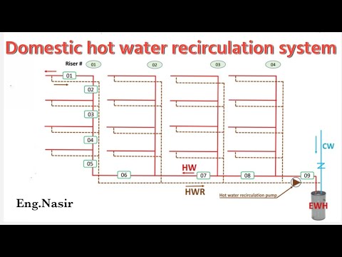
Take a twelve-storey residential riser at 3.0 m floor to floor: 36 m of hot flow riser at 7 W/m loses 252 W. At the 5 K spread W 551 allows, and with water near 57.5 °C (ρ 984.6 kg/m³, cp 4.185 kJ/kg·K), that riser needs 44 L/h. Six such risers plus 90 m of basement distribution at 11 W/m come to 2,502 W, or 437 L/h through the collected main back to the heater. Those two numbers, 44 and 437, are what the rest of the design is built on.
Notice how small they are. A riser return carrying 44 L/h moves less than a slow tap, and that is the correct answer. It is also why the next step catches designers out.
| Standing heat loss of the insulated run (W) | 5 K spread (W 551 duty) | 10 K spread (non-compliant) |
|---|---|---|
| 252 | 44 | 22 |
| 990 | 173 | 86 |
| 1512 | 264 | 132 |
| 2502 | 437 | 219 |
Step 3: Read the Velocity Window for What It Is
German circulation practice under W 553 designs the flow velocity in the circulation pipe at 0.2 m/s to 0.5 m/s, and allows a maximum of 1.0 m/s only where pumps with relatively high heads are available. The same practice splits that window by position in the loop: pipes near the circulation pump are sized for 0.5 m/s, or 1.0 m/s with a high-head pump, while pipes further from the pump are operated at a maximum of 0.3 m/s. Circulation pipes must also carry a minimum internal diameter of 10 mm.
Read those three rules together and the window stops being a uniform target. Velocity is designed to fall as you move outward from the pump, because each riser take-off removes flow from the main. The 0.5 m/s figure is a sizing target for the collected main; the 0.3 m/s figure is a ceiling for the outer legs; the 10 mm bore is a floor that applies everywhere.
Now put the riser number into it. At 44 L/h, a PP-R dn20 S3.2 return with a 14.4 mm bore runs at 0.075 m/s. Go thinner-walled to dn20 S5 (16.2 mm) and it falls to 0.059 m/s. Go up to dn25 S3.2 (18.0 mm) and it falls again to 0.048 m/s. To reach 0.2 m/s at that flow the bore would have to shrink to 8.8 mm, which is below the 10 mm minimum. Even in a 10 mm bore the same 44 L/h only reaches 0.156 m/s.
The instruction to hold 0.2 m/s in every return is therefore unachievable on a branch riser in any standard PP-R size, and chasing it produces the wrong design: a bore too small to be legal, or a flow rate inflated past the 5 K duty to force the velocity up. What holds a riser hot is the flow the heat balance demands, delivered by a balancing valve. Velocity is checked where the rule applies, which is the main.
The cost of the wrong reading is measurable. Forcing 0.2 m/s through a 14.4 mm bore means pushing 117 L/h down that riser instead of 44 L/h, roughly 2.7 times the flow the heat balance calls for. Six risers treated that way take the collected main from 437 L/h to about 877 L/h — six forced risers at 117 L/h plus the 173 L/h the distribution run still contributes — so the pump duty and the main double to meet a demand nothing in the standard asked for. The hygiene outcome does not improve, because the return was already arriving at 55 °C.
| Return option | Bore (mm) | Velocity (m/s) | Verdict |
|---|---|---|---|
| Theoretical bore for 0.2 m/s | 8.8 | 0.200 | Not permitted: under the 10 mm floor |
| Minimum legal bore | 10.0 | 0.156 | Still under 0.2; the window does not apply here |
| PP-R dn20 S3.2 | 14.4 | 0.075 | Specify this: smallest bore, valve sets the flow |
| PP-R dn20 S5 | 16.2 | 0.059 | Acceptable; check the series suits 60 °C duty |
| PP-R dn25 S3.2 | 18.0 | 0.048 | Oversized for a branch return; extra standing loss |
Step 4: Size the Collected Main in PP-R Bores, Not in Nominal Sizes
PP-R is ordered by outside diameter and flows by inside diameter, and the gap between the two is wider than in metal pipe. At dn25 the bore is 18.0 mm in series S3.2 and 20.4 mm in S5; at dn32 it is 23.2 mm and 26.2 mm. A circulation line called up as “25 mm PP-R” on a drawing, with no series, is not a sized line. Our PP-R size, SDR and PN reference sets out the full matrix.
Run the 437 L/h main through the candidate sizes with Colebrook–White at an absolute roughness of 0.007 mm, the same basis as our published PP-R flow chart, and the decision makes itself. dn25 S3.2 lands at 0.477 m/s, sitting on the 0.5 m/s near-pump target, and costs 172 Pa per metre. dn32 S3.2 falls to 0.287 m/s at 51 Pa/m, inside the window but slack for a pump-adjacent section. dn40 S3.2 drops to 0.184 m/s, under the 0.2 m/s floor. One size too far and the main leaves the window entirely.
Going the other way costs pump head. dn20 S3.2 reaches 0.746 m/s, still under the 1.0 m/s absolute ceiling, but at 502 Pa/m it burns roughly three times the gradient of dn25 over the same run. That is the trade the high-head clause is describing, and it is a defensible choice only when the pump is selected for it.
One more trap sits in the divisor. Designers used to heating circuits reach for a 10 K spread out of habit. On the same 2,502 W loop that halves the flow to 219 L/h and puts dn25 S3.2 at 0.239 m/s — still inside the velocity window, still apparently legal. The water, however, now returns 10 K below the heater outlet, breaking the 5 K clause. A hydraulic assumption has produced a temperature failure that no velocity check will catch.
| PP-R size and series | Bore (mm) | Velocity (m/s) | Gradient (Pa/m) | Verdict |
|---|---|---|---|---|
| dn20 S3.2 | 14.4 | 0.746 | 502 | Only with a high-head pump selected for it |
| dn25 S3.2 | 18.0 | 0.477 | 172 | Specify this: on the 0.5 m/s near-pump target |
| dn32 S3.2 | 23.2 | 0.287 | 51 | Use for outer legs held under 0.3 m/s |
| dn40 S3.2 | 29.0 | 0.184 | Reject: under the 0.2 m/s window floor |
Step 5: Balance the Risers, Because the Loop Will Not Do It Itself
Six risers hanging off one main do not share 437 L/h evenly. Water takes the path of least resistance, so the riser closest to the pump over-circulates and the furthest one is starved. German practice is explicit that the circulation volume flow for each riser must be calculated and set with a balancing valve, a Strangregulierventil, on each return before it joins the main.
The failure mode is quiet and expensive. An unbalanced loop still shows 55 °C at the plant-room return, because the near risers are pushing enough hot water back to hold the mixed temperature up. The far riser sits at 48 °C, and nobody finds out until a sentinel-outlet check during commissioning or a water-safety audit two years later. At that point the remedy is retrofitting valves into a riser shaft that has been boarded and decorated.
Three things belong on the drawing so that this gets set rather than guessed:
- The circulation flow for each riser in L/h — 44 in the worked example — written next to its valve.
- The valve model and its setting, rather than the words “balancing valve” on a symbol.
- The S-series on every circulation line as well as every supply line. An installer cannot infer 14.4 mm from “dn20”, and a line whose series is unstated gets bought on price: the thinnest wall in stock moves the bore by nearly 2 mm and the velocity with it.
Expansion needs the same treatment on a line held at 60 °C continuously. A circulation return is hot every hour of the year, so it cycles less than a supply line but sits at its design temperature permanently; our guidance on PP-R support spacing and thermal expansion covers the bracket schedule that follows from that.
Where PP-R Changes the Answer, and What We Check Before the Pipe Ships
Two properties of PP-R matter to a circulation loop specifically. The first is the bore. Because the wall is thick relative to the outside diameter, a PP-R circulation main holds velocity in a smaller nominal size than a metal equivalent would, which is why dn25 rather than dn32 lands on the near-pump target at 437 L/h.
The second is the joint. Socket heat fusion produces a homogeneous weld with no elastomeric seal inside it, so a line that runs at 60 °C every hour of its life carries no seal as a wear part. The EN ISO 15874 service classes are where the continuous-duty rating is declared, and a circulation loop should be specified against the class that matches it.
The checks that protect this design happen before dispatch. Resin is verified before extrusion. Outside diameter, wall thickness at multiple points and ovality are checked against the S-series tables, which is the same number the hydraulic calculation depends on. Pipes, fittings and fused joint assemblies are pressure-tested on in-house hydrostatic benches against DIN and EN ISO thresholds. The PP-R range carries a DVGW type examination for drinking-water pipe and SKZ testing on pressure pipe and fittings; certificate references come on request, so a buyer verifies them in the issuing body’s directory.
What we cannot do is publish a per-size wall and SDR matrix in an article. That table belongs to the current technical datasheet and it moves; quoting a stale one into a submittal is how a bore assumption becomes a velocity error. Ask for the live version, in writing, against the sizes on your schedule. The PP-R pipe and fittings range covers OD 20–110 mm in standard, fibre-reinforced, aluminium-composite and copper-lined constructions.
Conclusion
The chain is short: heat loss in watts, divided by the 5 K the hygiene rule allows, gives litres per hour; the PP-R bore turns litres per hour into a velocity; the velocity check applies to the collected main, and the balancing valve does the work on each riser.
The risk worth naming is the one that hides. A loop sized on a 10 K spread, or a return chased up to 0.2 m/s in a bore that cannot legally exist, passes every hydraulic review and fails a temperature audit years later, embedded in a riser shaft nobody wants to open. Fix the temperature duty first, write the S-series and the per-riser flow on the drawing, and ask your supplier for the live wall table before the schedule is issued.
Frequently Asked Questions
What is the minimum flow velocity in a hot water circulation return?
German circulation practice under W 553 designs the circulation pipe at 0.2–0.5 m/s, with 1.0 m/s as an absolute maximum where a high-head pump is used. The window applies to the collected main; branch riser returns run far slower and are controlled by their balancing valves.
What return temperature does DVGW W 551 require?
W 551 (2004-04) allows no more than a 5 K drop between the heater outlet and the point the circulation line re-enters the heater. With the required 60 °C outlet, the return floor is 55 °C. The UK equivalent under HSE HSG274 Part 2 is a calorifier return not below 50 °C.
How do I calculate the circulation flow rate for a riser?
Use V = Q ÷ (ρ · cp · Δθ). A 36 m riser at the 7 W/m planning figure loses 252 W, which at a 5 K spread needs 44 L/h. Use your project’s insulation schedule for Q wherever one exists, because the 7 and 11 W/m figures are an EnEV-era convention.
What size PP-R pipe should a circulation main be?
Size it on the bore, not the nominal number. At 437 L/h, PP-R dn25 S3.2 (18.0 mm bore) gives 0.477 m/s at 172 Pa/m and sits on the near-pump target, while dn40 S3.2 falls to 0.184 m/s and drops out of the window. Always state the S-series on the drawing.
Is DVGW W 551-1 in force yet?
No. As of 13 September 2026 it remains a draft, listed by the publisher as Entwurf 05/2026, and W 551 (2004-04) is the document in force. The draft would permit circulation at 55/50 °C under monitoring conditions for heat-pump systems, but that provision cannot be specified today.
Does PP-R pipe help control Legionella in a recirculation system?
No pipe material controls it. Every parameter that does — storage and delivery temperature, the 5 K circulation spread, dead-leg removal and flushing regimes — is a property of the system’s design and operation. Our review of antibacterial pipe claims in hotels and hospitals works through the evidence.