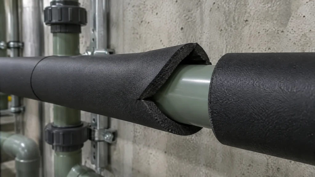
A PPR pipe insulation heat loss calculation usually gets run after the damage: a code table that does not list your case, or an insulation quote at a thickness nobody can justify. A 100 m run of bare 32 mm PP-R at 60 °C in a 20 °C plant room loses about 33,700 kWh a year; under 20 mm of lagging, about 7,850 kWh.
The method is EN ISO 12241:2022: heat flow per metre equals the temperature difference divided by three resistances in series, the PP-R wall, the insulation and the air film on the outer surface. For a 32 x 5.4 mm PP-R hot line under 20 mm of 0.035 W/(m·K) lagging that gives 9.0 W/m, against 38.5 W/m bare. Every figure below is a still-air model result on published PP-R property data, not a field measurement and not a Hitze test.
Key Takeaways
- q = Δθ ÷ (Rpipe + Rinsulation + Rsurface); each layer R = ln(De/Di) ÷ (2πλ); surface R = 1 ÷ (π·De·hse).
- The #1 page for this query omits the surface film: its example claims 989 W/m; with the film it is 203 W/m.
- 32 x 5.4 mm PP-R at 60 °C in 20 °C air: 38.5 W/m bare, 13.6 at 9 mm, 9.0 at 20 mm, 6.3 at 40 mm (λ 0.035).
- The PP-R wall is worth 1.0 mm of lagging on a 32 mm pipe, 2.0 mm on a 63 mm pipe.
- 63 x 10.5 mm at 6 °C in 25 °C / 80% RH air: 12 mm of elastomeric foam clears the 21.3 °C dew point; bright foil needs 28 mm.
- The same chain is your GEG Anlage 8 Nummer 4 or ASHRAE 90.1 footnote e documentation.

What the Calculation Must Include, and What the Top Result Leaves Out
The page that currently ranks first for this query computes conduction through a bare 110 mm PP-R wall with Q = 2πkL(T1 − T2) ÷ ln(r2/r1), no surface film and no insulation. It reports 9,889.61 W for 10 m at a 60 K difference: 989 W per metre. Rerun the same pipe with the outer air film in the chain and it loses 203 W/m at a surface temperature of 64.5 °C. The wall-only formula overstates it 4.9 times.
The rulebook is EN ISO 12241:2022, the current edition; the 2008 text is withdrawn. Formula 6 gives each cylindrical layer a linear resistance of ln(De/Di) ÷ (2πλ), Formula 8 adds the layers, and Formula 18 closes the chain with the surface film, hse(θse − θa). Drop the film and the answer is wrong by a factor, not a percentage.
Step 1: Fix the Inputs
PP-R is sold by outside diameter and SDR, but the resistance depends on the wall. To DIN 8077 a PN 20 (SDR 6) pipe of 32 mm has a 5.4 mm wall and a 63 mm pipe has 10.5 mm. Published PP-R data sheets put the material’s conductivity at 0.23 W/(m·K) at 23 °C to DIN 52612-1; that is generic property data, not a Hitze measurement.
Take the insulation conductivity at the mean temperature of the layer, never the catalogue headline. Armacell’s AF/Armaflex sheet states the tube value as [33 + 0.1·θm + 0.0008·θm²] ÷ 1000 W/(m·K): 0.033 at 0 °C, 0.0383 at a 40 °C mean. ROCKWOOL’s RockLap H&V stone-wool sections list 0.033 at 10 °C, 0.037 at 50 °C and 0.044 at 100 °C. A 60 °C line under lagging runs a mean near 40 °C, so the 0 °C figure flatters the result by about 15%.
Two inputs set the surface film: the finish and the room. Plastic, paint and elastomeric skins radiate at an emissivity near 0.9, bright aluminium foil near 0.05. A hot line needs the air temperature; a chilled line also needs the relative humidity, because its design condition is a surface that never drops below the dew point.

Step 2: Add the Resistances and Find the Surface Coefficient
For the 32 x 5.4 mm hot line under 20 mm of 0.035 lagging the chain reads: wall ln(32/21.2) ÷ (2π × 0.23) = 0.285 m·K/W; lagging ln(72/32) ÷ (2π × 0.035) = 3.688; surface 1 ÷ (π × 0.072 × 8.95) = 0.494. Total 4.467 m·K/W, so q = 40 K ÷ 4.467 = 9.0 W/m. The lagging carries 83% of the resistance, the air film 11%, the wall 6%.
The surface coefficient hse is the part people guess. ISO 12241 builds it from a radiative part plus a convective part. Radiation is ε × 5.67 × 10-8 × 4Tav³, about 5.3 W/(m²·K) at ε 0.9 and 0.3 at ε 0.05 near room temperature. Convection on a small horizontal pipe in still air follows the laminar form 1.32 × (Δθ/De)0.25, about 3.7 W/(m²·K) for a 72 mm surface running 4.4 K warm. Together, roughly 9 W/(m²·K) for a non-metallic finish and roughly 4 for bright foil.
The standard’s shortcut, hse = CA + 0.05·Δθ with CA = 8.5 for non-metallic surfaces, gives 8.7 W/(m²·K) here, within 4%, though it is stated for pipes of 0.25 to 1.0 m outer diameter. Since Δθ depends on the surface temperature you are solving for, iterate twice; hse of 8 or 10 instead of 8.95 only shifts the 20 mm result from 8.84 to 9.06 W/m.
Step 3: Hot Case, 32 mm PP-R at 60 °C
Run the chain at each thickness and the curve flattens fast. Bare, the 32 x 5.4 mm pipe loses 38.5 W/m with its skin at 49.0 °C. The first 9 mm of 0.035 lagging cuts that to 13.6 W/m; 20 mm reaches 9.0 W/m; the step from 20 to 40 mm buys only 2.7 W/m more. Over 100 m that is 33,700 kWh a year bare, 11,900 at 9 mm and 7,850 at 20 mm.
| Insulation thickness (mm) | λ 0.035 code basis (W/m) | Elastomeric, ε 0.9 (W/m) | Foil-faced stone wool, ε 0.05 (W/m) | Surface temp, λ 0.035 (°C) |
|---|---|---|---|---|
| 0 (bare) | 38.5 | 38.5 | n/a | 49.0 |
| 9 | 13.6 | 14.7 | 12.0 | 28.5 |
| 13 | 11.2 | 12.2 | 10.3 | 26.4 |
| 20 | 9.0 | 9.7 | 8.5 | 24.4 |
| 25 | 8.0 | 8.7 | 7.6 | 23.6 |
| 30 | 7.3 | 7.9 | 7.0 | 23.0 |
| 40 | 6.3 | 6.9 | 6.2 | 22.2 |
Two things in that table matter for a PP-R specification. The material columns sit within 1 W/m of the code column from 20 mm up: elastomeric runs hotter inside and slightly worse, foil-faced wool gains from its low emissivity. And the PP-R wall’s 0.285 m·K/W equals 1.0 mm of 0.035 lagging on this pipe, 2.0 mm on a 63 x 10.5 mm pipe. German and US rules both let you count it; it replaces a millimetre or two, not a layer.
Step 4: Chilled Case, 63 mm PP-R at 6 °C, Surface Above the Dew Point
On a chilled line the number that matters is the outer surface temperature: below the dew point it sweats, drips onto ceilings and soaks mineral wool until it insulates like a sponge. At 25 °C and 80% RH the dew point is 21.3 °C; ISO 12241 Table 3 puts it the other way round, a surface at most 3.7 K below the air at 24 to 26 °C and 80% RH.
Run the 63 x 10.5 mm pipe at 6 °C through the same chain and watch the surface. Bare, it sits at 12.8 °C and streams. Under 9 mm of elastomeric foam it reaches 20.5 °C, still 0.8 K short; 13 mm lifts it to 21.6 °C and the line stays dry. The minimum is 12 mm, at a heat gain of 8.7 W/m.
| Insulation thickness (mm) | Elastomeric, ε 0.9: surface (°C) | Foil-faced wool, ε 0.05: surface (°C) | Verdict at 80% RH |
|---|---|---|---|
| 0 (bare) | 12.8 | 10.4 | Condenses on both |
| 9 | 20.5 | 17.7 | Condenses on both |
| 13 | 21.6 | 19.0 | Elastomeric dry; foil condenses |
| 19 | 22.5 | 20.2 | Elastomeric dry; foil condenses |
| 25 | 23.0 | 21.0 | Elastomeric dry; foil 0.3 K short |
| 32 | 23.4 | 21.7 | Both dry |
Installers are usually surprised by the foil column. A bright finish that saves about 9% on a hot pipe works against you on a cold one. A low-emissivity skin exchanges less heat with the room, so it sits closer to the water temperature and needs 28 mm of stone wool to clear the dew point where 12 mm of foam will do. BS 5422:2023’s condensation tables, in ROCKWOOL’s selection, run the same way: 20 mm on a high-emissivity surface against 40 mm on a low-emissivity one for a pipe up to 60.3 mm at 5 °C.
Treat the chilled result as a floor: ISO 12241’s own introduction warns that dew formation cannot be reliably assured from basic calculations because local humidity varies, and 85% RH cuts the allowed difference to 2.6 K. Size for the worst week.
Step 5: Code Equivalence and Elastomeric vs Mineral Wool
The model earns its keep when the code table does not fit your material. GEG Anlage 8 states every thickness for a 0.035 W/(m·K) product; Nummer 3 says to convert for anything else by recognised calculation methods. Hold the lagging resistance constant, ln(72/32) ÷ 0.035 = 23.17, and the 20 mm band on the 32 mm pipe becomes 22.9 mm of elastomeric at its 40 °C conductivity of 0.0383, or 21.7 mm of foil-faced stone wool at 0.037. Nummer 4 lets you claim equivalence while counting the pipe wall, the 1.0 mm from Step 3.
ASHRAE 90.1 does the same job in inches. Table 6.8.3-1 of Addendum aq to the 2019 edition requires 1.0 in (25.4 mm) on a pipe under 1½ in at 105 to 140 °F, assuming 0.22 to 0.28 Btu·in/(h·ft²·°F) at a 100 °F mean, which is 0.0317 to 0.0404 W/(m·K). Elastomeric at that mean is 0.263 and stone wool about 0.248 in those units, both inside the range, so the table value stands and lands at 7.9 W/m on the hot curve. Outside the range, footnote a gives T = r{(1 + t/r)K/k − 1}.
Footnote e is the PP-R clause: a non-metallic pipe with more thermal resistance than steel may carry less insulation if you document that pipe plus lagging transfers no more heat per foot than steel with the table thickness. The chain above is that documentation; edition and adoption vary by state, so confirm which 90.1 the authority having jurisdiction enforces.
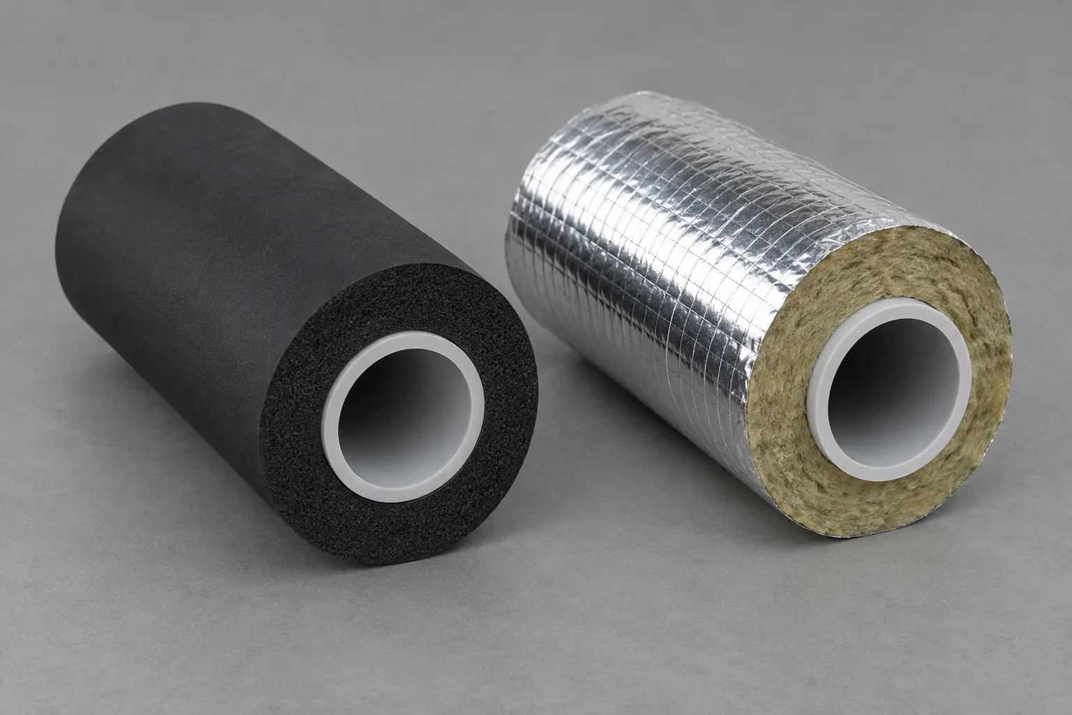
| Property | Elastomeric foam (AF/Armaflex) | Stone-wool section (RockLap H&V) | Verdict for PP-R |
|---|---|---|---|
| Conductivity λ (W/m·K) | 0.033 at 0 °C; 0.0383 at 40 °C mean | 0.033 at 10 °C; 0.037 at 50 °C; 0.044 at 100 °C | Equal at chilled means; wool edges ahead hot |
| Vapour resistance | Closed cell, μ ≥ 10,000; no separate barrier | Fibrous; relies on foil facing and taped joints | Elastomeric on chilled lines |
| Service temperature (°C) | −50 to +110 | 0 to 250; foil face limited to 80 | Either covers PP-R’s hot-water duty |
| Finish emissivity | About 0.9 (black skin) | About 0.05 (bright foil) | Foil cuts hot loss about 9%; hurts chilled |
| Dew-point thickness, 63 mm at 6 °C (mm) | 12 | 28 | Elastomeric, by a wide margin |
The verdict follows the two cases. Chilled and cold-water PP-R gets closed-cell elastomeric: its own vapour resistance does the barrier’s job, and 12 mm clears the dew point where the foil-faced section needs 28 mm. Heating and hot-water PP-R can take either; foil-faced stone wool loses about 9% less at the same thickness, elastomeric fits faster around fused sockets and bends.
What to Ask the Pipe Supplier, and What We Check
Every input on the pipe side of the chain is a supplier data point. Ask for the per-size wall and SDR from the current technical data sheet, not a catalogue OD list, because the 1 to 2 mm the wall is worth under Nummer 4 or footnote e depends on it. Ask which construction the run uses, too: fibre-reinforced and aluminium-composite pipes carry different walls, as the construction comparison sets out.
What Hitze checks before a pipe leaves the plant
Hitze’s PP-R is made to DIN 8077/8078 and EN ISO 15874, with SKZ testing on pipe and fittings and a DVGW type examination on the drinking-water line. Its in-house checks measure OD, wall at multiple points and ovality against the S-series tables on every size from OD 20 to 110 mm before hydrostatic testing, which is the dimensional record an equivalence file needs. The project piping supply page covers how sizes and constructions are matched to a tender, the SDR and PN ratings guide explains the wall classes, and the insulation decision guide settles which code duty applies first.

Conclusion
Do it in this order. One: fix the six inputs, with the insulation conductivity at its mean temperature and the finish emissivity chosen honestly. Two: build the three-resistance chain and iterate the surface temperature twice. Three: on a hot line, stop where the next 10 mm buys under 1 W/m. Four: on a chilled line, size to the dew point at the worst humidity anyone will commit to; bright foil needs more, not less. Five: file the chain as your Nummer 4 or footnote e documentation, counting the pipe wall at 1 to 2 mm. The answer flips only outdoors or in moving air, where still-air coefficients no longer apply.
Before you sign the thickness, pull the wall table for the exact SDR you are installing and rerun Step 2 with it.
Frequently Asked Questions
How do I calculate the heat loss through pipe insulation on a PPR pipe?
Divide the water-to-air temperature difference by the sum of three resistances per metre: the PP-R wall ln(Do/Di)/(2πλ), the insulation ln(De/Do)/(2πλ), and the surface film 1/(π·De·hse), per EN ISO 12241:2022. For 32 x 5.4 mm PP-R at 60 °C under 20 mm of 0.035 lagging that gives 9.0 W/m.
Does the PPR pipe wall count as insulation?
It counts, but for very little: at 0.23 W/(m·K) the wall of a 32 x 5.4 mm pipe equals 1.0 mm of 0.035 lagging, and a 63 x 10.5 mm wall equals 2.0 mm. GEG Anlage 8 Nummer 4 and ASHRAE 90.1 footnote e both let you include it in an equivalence calculation.
What surface heat transfer coefficient should I use for an indoor pipe?
About 9 W/(m²·K) for a plastic, painted or elastomeric finish and about 4 W/(m²·K) for bright foil in still air, from radiation plus laminar convection. ISO 12241’s shortcut hse = CA + 0.05·Δθ, with CA = 8.5 for non-metallic surfaces, lands within 4% of that for the hot case here.
Why does foil-faced insulation need to be thicker on a chilled PPR line?
A low-emissivity foil exchanges less heat with the room, so its surface sits closer to the cold water and drops below the dew point sooner. On a 63 mm PP-R line at 6 °C in 25 °C, 80% RH air, 12 mm of elastomeric foam clears 21.3 °C but foil-faced stone wool needs 28 mm.
Which insulation conductivity value goes into the calculation?
The value at the mean temperature of the layer, which is what GEG Anlage 8 also prescribes: 40 °C for heating lines and 10 °C for cold lines. AF/Armaflex declares 0.033 W/(m·K) at 0 °C but 0.0383 at 40 °C; RockLap H&V is 0.033 at 10 °C and 0.037 at 50 °C.


