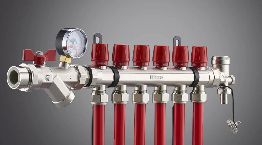
Underfloor heating manifold installation is the part of a radiant job where mistakes stop being cheap. Everything upstream of the manifold is recoverable — a wrongly ordered coil goes back, a mispositioned cabinet gets moved. Everything downstream of it disappears under 45 mm of screed the moment the pour starts, and the only evidence you will ever have that the loops were sound is a pressure gauge reading taken before the screed truck arrived. That is why the sequence matters more than the workmanship on any single joint.
The European installation standard for this work is BS EN 1264-4:2021, published 31 May 2021, which sets uniform requirements for the construction of embedded heating floors. It is also, for most installers, a document they have never opened — so the numbers that actually govern their job arrive second-hand through a merchant’s leaflet.
This guide works from the standard and from named manufacturers’ technical documentation instead, and it is explicit about the two figures every generic version of this article invents. On the tightening torque of a Eurocone nut, the answer is that no standard figure exists, and EN 16313 says why. On the test pressure the manifold left the factory at, published manufacturer data gives 6 bar at 20 °C. Both are set out in full, with the sources, in the sections below.

Key Takeaways
- Port count follows loop count, not room count: one loop uses one flow port and one return port. Hitze supplies 2 to 12 ports in brass and stainless on the same matrix.
- The heating-side strength test under DIN 18380 is cold water at minimum 4 to maximum 6 bar held 60 minutes with no drop — not the 11 bar / 30 minute test that applies to drinking-water pipework under DIN EN 806-4.
- Loops stay pressurised through the pour. KAN-therm specifies a minimum of 3 bar with 6 bar recommended during screed laying; Uponor requires the pipes to be under operating pressure.
- Screed cover above the pipe is 45 mm for cement and 35 mm for anhydrite at payloads up to 2 kN/m², per DIN 18560 Table 1.
- Functional heating starts no earlier than 21 days after a cement screed or 7 days after anhydrite: 25 °C flow for 3 days, then maximum design flow temperature for 4 days.
- Functional heating is a function test under VOB / DIN 18380. It is not screed drying, and treating it as drying is how flooring gets laid over wet screed.
- There is no standard Eurocone torque: EN 16313:2013 standardises the connection’s geometry only, not tightening force. Work to the figure on your manifold manufacturer’s instruction sheet.
- Manifolds are factory pressure tested before shipping — published manufacturer data puts it at 6 bar at 20 °C per DIN EN 1264-4, against a typical operating pressure under 3 bar.
The install sequence that decides whether a radiant job is recoverable
A manifold install is not really an assembly task, it is a sequencing task. The physical work — hanging two bars on brackets, tightening a row of compression nuts, connecting a flow and return — is within reach of any competent heating engineer. What separates a job that hands over cleanly from one that generates a callback eighteen months later is whether each verification step happened while it was still possible to act on the result.
There is exactly one irreversible moment in the process: the screed pour. Before it, a weeping olive costs you ten minutes and a new one. After it, the same olive costs a thermal-imaging survey, a broken floor and an argument about who pays. This is why the standards put the pressure test before the screed and require the pressure to be held through the pour — not as belt-and-braces, but because a leak that appears during the pour can still be traced to a visible joint, while one that appears afterwards cannot.
The sequence below is written in that order deliberately. Skipping ahead is the classic failure: connecting loops before confirming the manifold position leaves you cutting pipe short at the bars, and pouring screed before the test protocol is signed means nobody can later say whether the leak predated the screeder or was caused by him.
Every step before the pour is cheap to redo. Every step after it is a demolition job. Sequence accordingly.
Set the manifold position and port count before anything is fixed
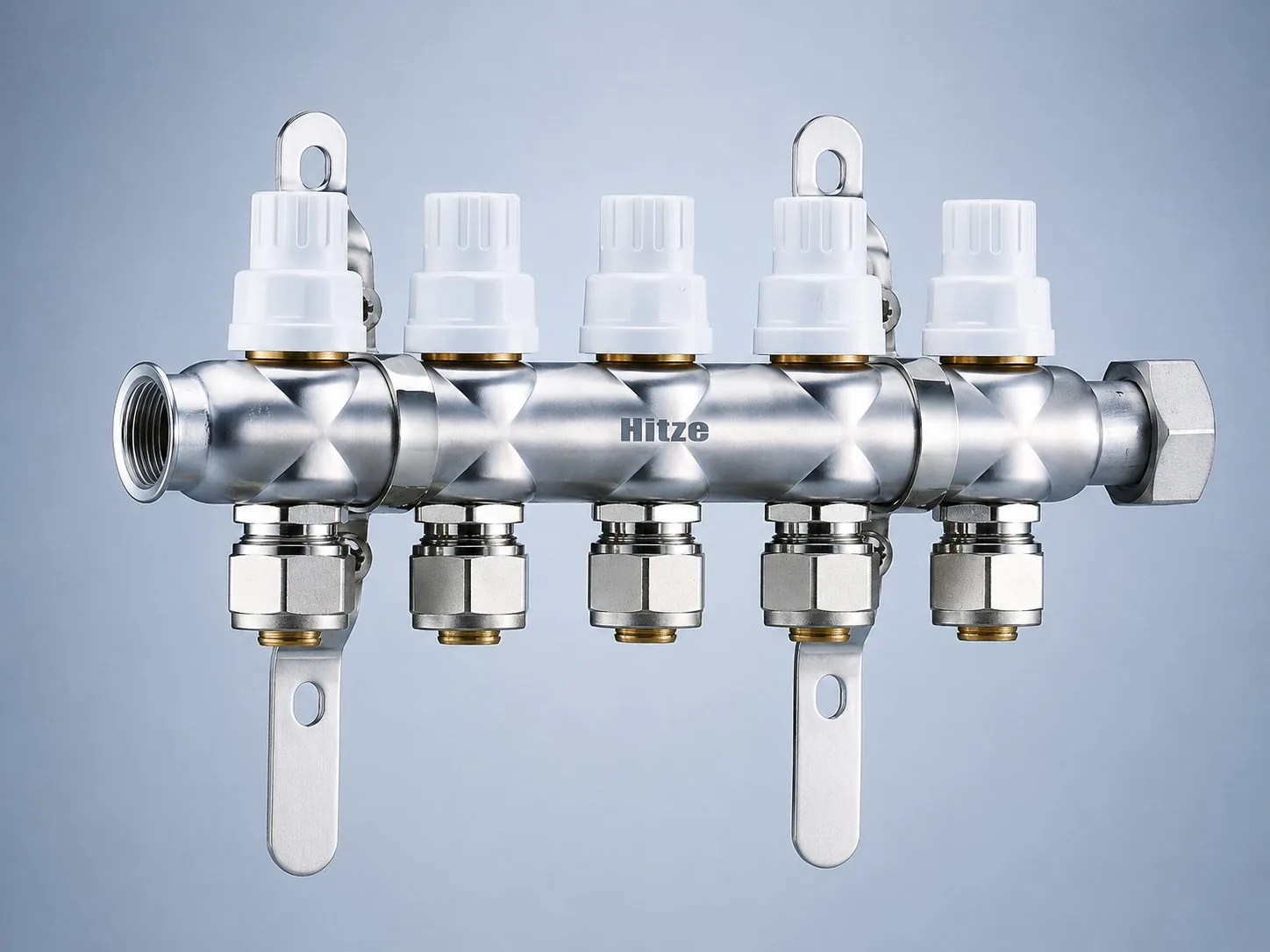
Port count follows loop count, and loop count follows floor area — not room count. That distinction catches people out constantly, because a large open-plan kitchen-diner is one room and frequently three loops.
The published Hitze rule of thumb is to keep each loop to roughly 100 m of pipe, which at 150 mm spacing covers something like 15 to 20 m² of floor, varying with a pitch of 100–200 mm and pipe diameter of 16 or 20 mm. Hitze flags that as a starting point to be confirmed against a heat-loss calculation, and that hedge is worth keeping: the number is a sanity check on a design, not a substitute for one.
The reason loop length is capped at all is hydraulic, not thermal.
KAN-therm’s surface-heating guidebook puts the ceiling plainly — total pressure drop across a manifold circuit should not exceed 20 kPa — and publishes approximate maximum circuit lengths that scale with bore: 60 m at 12 × 2 mm, 100 m at 16 × 2 mm, 120 m at 18 × 2 mm and 160 m at 20 × 2 mm, inclusive of the tails back to the manifold. Those are that manufacturer’s figures for that manufacturer’s pipe, but they show the shape of the relationship: go up one pipe size and you buy a substantially longer loop, which is often cheaper than buying more manifold ports.
Coil length is the constraint people forget at ordering stage. A 100 m loop has to come off a single coil or it carries a buried joint, and a buried joint under screed is the one thing every warranty conversation eventually circles back to.
Hitze supplies 16 × 2.0 mm in 200 m coils and 20 × 2.0 mm in 300 m coils, so a pair of 100 m loops comes out of one 16 mm coil with nothing left buried. If the design produces a 105 m loop and the coil is 100 m, the answer is to redesign the loop, not to add a coupler.
Position is the other decision that must be made before anything is drilled. The manifold wants to be reasonably central to the loops it serves, because every metre of tail from the manifold to the heated area is pipe length consumed inside the loop budget without heating anything.
It also needs to stay accessible for the life of the system — flow meters get rebalanced, actuators fail, isolation valves get closed for a repair. Trade practice typically sets the bars roughly 300–500 mm above finished floor level, which is an estimate rather than a standards figure; there is no EN 1264 clause on mounting height. What the standard does pin down is the far more consequential number on the other side of the wall: the edge joint has to give the screed 5 mm of movement, and the edging strip has to be held in position while the screed goes in.
| Decision | Figure to work to | Source |
|---|---|---|
| Loop length ceiling | ~100 m rule of thumb; confirm by heat-loss calc | Hitze published guidance |
| Circuit pressure drop | ≤ 20 kPa per circuit | KAN-therm guidebook |
| Ports per loop | 1 flow + 1 return; 2–12 port range | Hitze product data |
| Floor surface temp cap | 29 °C occupied, 35 °C edge, 33 °C bathrooms | EN 1264 |
| Edge joint movement | 5 mm for the load distribution layer | DIN 18560 / EN 1264-4 |
Those floor-surface caps are the reason a manifold decision is also a comfort decision. EN 1264 limits the occupied area to 29 °C, the edge zone to 35 °C and bathrooms to 33 °C.
If a design needs more output than those caps allow at your chosen spacing, the fix is tighter pipe pitch or another loop — which is another port — not a hotter flow temperature. Deciding that after the manifold is on the wall means buying a second manifold. If you are still choosing between port counts and materials, the brass versus stainless sizing guide covers that selection in detail.
Mount the bars square and leave yourself room to work
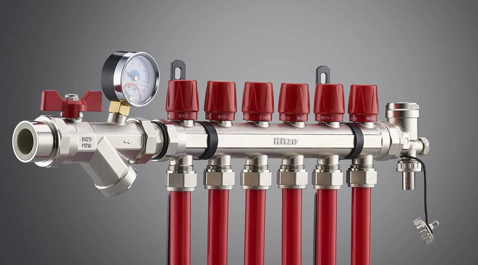
A manifold set ships as a working assembly rather than two bars of metal. On a Hitze stainless set that means flow meters already on the supply bar, balancing valves on the return, end caps, air vents and mounting brackets fitted, and the whole thing pressure-tested and boxed before it left the plant.
The practical consequence for the installer is that the bars arrive at a fixed centre distance and must be hung to that spacing — the brackets set the geometry, and forcing the bars apart to suit a bracket you have already fixed is how a set arrives on site square and leaves it strained.
Level matters more than it looks
The bars need to be level for a reason that only becomes visible at commissioning. The flow meters are float-type sight gauges — on Hitze stainless sets, 0–2.5 L/min — and a float reads against a graduated scale under gravity. Hang the bar out of level and every reading on it carries a consistent offset, which means an installer balancing to design flow rates is balancing to a lie. It is not a catastrophic error, but it is an invisible one, and it will be blamed on the manifold rather than on the spirit level.
Body size scales with port count
Hitze manifold bodies are 1″ up to around four ports and 1¼″ from eight ports up, with six ports available either way. This is not cosmetic: the main body has to carry the summed flow of every loop hanging off it, so a twelve-port bar on a 1″ body would throttle the whole floor at the manifold.
When you specify by port count you are implicitly specifying a body bore, and the flow and return connection into the plant room has to match it. Discovering that mismatch after the primary pipework is run is a genuinely annoying half-day.
Leave service access, not just clearance
There is a difference between fitting the manifold into a cabinet and being able to work on it in one. An actuator has to come off vertically from the return bar. A flow meter cap needs a hand and a tool above it. A fill/drain valve needs a hose on it and somewhere for the water to go.
Cabinets that were sized to the manifold’s dimensions rather than to its service envelope are a recurring source of “we had to cut the cabinet” on handover day.
Connect the loops to the Eurocone ports without splitting an olive
Hitze loop outlets are ¾″ Eurocone, which is the interface that makes multilayer and PE-RT adaptors interchangeable across brands.
A Eurocone connection is a three-part assembly working in sequence: the nut goes on the pipe first, then the olive or split ring, then the support insert is driven into the bore of the pipe. The insert is what stops the plastic pipe collapsing when the nut compresses the olive around it. Assemble those three in the wrong order — and it is easy to slide the nut on after the olive — and you find out at the moment the joint has to come apart again.
Two preparation details do most of the work here. The pipe end has to be cut genuinely square, because a Eurocone seals on a short cylindrical land and an angled cut presents an ellipse to a circular seat.
And the cut end has to be reamed or at least deburred, because the support insert has to go fully home; an insert that stops 2 mm short leaves the olive compressing unsupported pipe wall. Both faults produce the same symptom, which is a joint that holds at test pressure and weeps at operating temperature once the polymer relaxes.
Now the first of the two figures this guide promised to be explicit about: the tightening torque. Here is the explicit answer — there is no standard Eurocone torque, and the reason is documented in the standard itself. The Eurocone port is governed by EN 16313:2013, “Connections for heating and cooling appliances — Detachable connection with outside threaded pipe G ¾ A and inside cone,” published in August 2013. That is the document manufacturers reference when they specify a loop nipple; the Ambiente stainless datasheet, for example, lists its connection nipples as “G¾ male thread, inner cone acc. to DIN EN 16313.”
Read what EN 16313 actually standardises and the torque question resolves itself. It specifies dimensions — the geometry of the single and the double connection — and nothing about tightening force. The standard exists because that geometry was previously not standardised at all. Its own rationale is blunt about the state it was written to fix: “So far, the designation ‘eurocone’ has conveyed the impression that there is a standardised geometry. However, this is not the case, that is, the screw in or thread lengths, the cone angles and diameters, as well as the diameter of the inner cylinder differ frequently.”
So a Eurocone is a dimensional interface that was harmonised in 2013, and even that harmonisation covers only shape. Torque was never in scope, because the force needed to seal the joint is not a property of the port — it is a property of the olive material, the insert design and the body the thread is cut into. A brass olive on a brass body and a stainless-bodied manifold do not want the same figure.
This is why the confident numbers in circulation — 50 Nm, “one and a half turns past hand tight” — trace back to individual retailers writing for their own fittings, with no standard behind them. Quoting one of those at a different manifold is not caution, it is transferring a figure across a boundary the standard explicitly does not cross.
The practical consequence is directional, and worth knowing even without a number. Over-torque splits the olive or galls the thread on a stainless body — and a galled stainless thread is not recoverable on site, it is a replaced bar. Under-torque leaves a joint that passes a cold test and weeps warm, which is the failure mode that surfaces after the screed is down.
Work to the instruction sheet supplied with your manifold, and if the set did not come with one, ask the supplier for it before you tighten anything. On a Hitze order, request the figure with the enquiry so it is in writing before the set ships rather than discovered on site.
Match the insert to the pipe, not to the port
The Eurocone thread is common; the insert bore is not. A 16 × 2.0 mm pipe and a 16 × 2.2 mm pipe have the same outside diameter and different internal bores, and an insert sized for one is loose or immovable in the other.
Because both pipes go into the same ¾″ Eurocone port, nothing about the connection tells you the wrong insert is fitted until the joint leaks.
Order adaptor sets against the pipe wall thickness you are actually laying, and if a job mixes wall thicknesses across sizes — which happens when a 16 mm floor loop meets 20 mm tails — keep them physically separated on site. Hitze publishes wall thicknesses of 2.0 to 4.4 mm across the 16 to 32 mm range, so this is not a hypothetical risk. The underfloor heating pipe range lists the size and coil combinations that pair with the manifold ports.
Label the loops before you connect them
Every loop must be identified at the manifold before the screed hides where it goes, and the label has to survive a wet trade.
The reason is balancing: flow rates are calculated per loop from that loop’s length and served area, so a manifold whose ports are connected in an unrecorded order cannot be balanced to design. It can only be balanced by trial and error across a heating season. Write the loop reference and its design flow rate on a durable tag at the port, and put the same information on the as-built drawing that goes in the handover pack.
Fill and purge one circuit at a time, not the whole manifold at once
Filling is where a lot of otherwise careful installs go wrong, because the instinctive approach — open everything and let the system fill — is the one method guaranteed to trap air. Water takes the path of least resistance, which means the shortest loop fills, the longest loop keeps an air pocket, and no amount of running the pump afterwards will shift it.
The documented method is the opposite: close both manifold isolation valves, connect a hose from mains supply to the flow fill/drain valve and another from the return fill/drain to a waste point, then open and close each circuit individually, one at a time, watching the discharge until clear water runs without bubbles before moving to the next.
Underfloor Heating Systems Ltd’s commissioning instructions are explicit about one thing installers routinely do anyway: do not fill the underfloor system from the boiler filling loop. The filling loop is sized for topping up a sealed system, not for pushing enough velocity through a 100 m coil to carry air out of it, and using it means accepting whatever air is left. Mains pressure through the manifold fill valves is what generates the flushing velocity that actually clears the loop.
Once the boiler flow and return are connected and the plumber has vented those, the isolation valves can be opened, and the same source specifies running the pumps for five minutes and then venting again at the bleed valve on the fill/drain assembly.
That second vent matters because dissolved air comes out of solution when the water is circulated and warmed, so a system that was genuinely air-free at fill will still surrender a pocket of air after its first proper circulation. Skipping it produces the classic symptom where the return bar never warms up despite the flow meters showing good flow.
A cold return bar with healthy flow-meter readings usually means trapped air or reversed flow and return — not a failed pump.
Pressure test to the right standard, and keep the pressure on
There are two different pressure tests in a plumbing and heating job and they are routinely confused, usually to the installer’s cost. For heating installations, Fränkische’s system documentation and its signed test-report template specify a strength test to DIN 18380 using cold water at a minimum of 4 to a maximum of 6 bar, held for 60 minutes, with no pressure drop.
For drinking-water pipework, DIN EN 806-4 requires a minimum of 11 bar held for 30 minutes. Those are separate tests for separate systems. Applying the 11 bar potable figure to a heating manifold rated to 6 bar working pressure is not thoroughness, it is an overpressure event on components that were never designed for it.
That 6 bar working-pressure figure is worth sitting with, because it is exactly where the DIN 18380 test tops out.
Hitze 304 stainless manifolds are rated to a working pressure of up to 6 bar and a working temperature of up to 80 °C. So the maximum permitted heating strength test sits right at the top of the manifold’s working range, not above it — which is the whole logic of that test band. Any guide telling you to test a UFH manifold at twice its working pressure is quoting a figure from somewhere else and has not checked it against the component rating.
The test pressure the manifold left the factory at
This is the second figure this guide promised to name, and it is the one that explains why the site test band looks the way it does. A manifold does not arrive untested. Published manufacturer data puts the production test at the same 6 bar: the Ambiente stainless datasheet states that “following assembly, manifolds are factory pressure tested to 6 bar,” that “every manifold is tested to 6 bar pressure (typical operating pressure would be less than 3 bar),” and lists a “Max. Test pressure at 20 °C: 6 bar (DIN EN 1264-4)” against continuous operating conditions of −10 °C to +70 °C at a maximum of 4 bar.
Line those three numbers up and the whole pressure story becomes one coherent picture rather than four unrelated figures. Roughly 3 bar or less is what the manifold actually sees in service. The factory proves each assembly at 6 bar at room temperature. The DIN 18380 site strength test tops out at that same 6 bar. The three are deliberately aligned: the test pressure is a proof figure set at the ceiling of the component’s rating, held cold, for a short period — it is not an operating condition and not a safety margin you are invited to spend.
Two things follow for the installer. First, the 6 bar you apply on site is not an extra stress the manifold has never met; it is a repeat, at ambient, of a proof the assembly already passed on a bench. That is why a factory joint weeping at first fill is genuinely unusual and points you at the connections made on site.
Second, and more usefully, this is the sourced answer to the guides that tell you to test a UFH manifold at 10 or 12 bar. Those figures exceed the manufacturer’s own stated maximum test pressure. Applying them does not prove the system is sound — it takes a component past the highest pressure its maker ever certified it against, and if something lets go you have created the defect you were testing for and voided the argument that it arrived faulty.
One caveat on transferring the number. That 6 bar is a named manufacturer’s published figure for a stainless manifold rated to DIN EN 1264-4, and it happens to coincide with both the DIN 18380 ceiling and the Hitze rating — but a proof pressure is a per-product value, not a universal constant. Manifolds built to a higher rating are proved higher. Read the figure off the datasheet for the set actually on your job; the point of this section is that the number exists and is published, so there is no reason to improvise it.
Frost is the other decision point. If the test period runs through freezing temperatures, or a long gap is expected between test and commissioning, a water test is the wrong tool — undrained water freezes and splits pipework and components.
The ZVSHK route is a tightness test with oil-free compressed air or inert gas at 150 mbar, held at least 120 minutes for up to 100 litres of pipe volume with a further 20 minutes for each additional 100 litres, followed by a strength test at a maximum of 3 bar for 10 minutes on nominal sizes up to 63 × 4.5 mm.
Note the gauge requirement that comes with it: the manometer must resolve 1 mbar for the tightness test, and 0.1 bar for the water strength test. A gauge that cannot resolve the drop you are looking for turns the test into theatre.
| Test | Pressure | Hold | Applies to |
|---|---|---|---|
| Strength, water (DIN 18380) | min 4 to max 6 bar, cold | 60 min, no drop | Heating systems |
| Strength, water (DIN EN 806-4) | min 11 bar | 30 min, no drop | Drinking water only |
| Tightness, air (ZVSHK) | 150 mbar | ≥120 min per 100 L | Frost risk / delayed start |
| During screed pour | min 3 bar, 6 bar recommended | Whole pour | All embedded loops |
The last row is the one that gets dropped. KAN-therm requires the loops to hold a minimum of 3 bar during screed laying and recommends 6 bar, and Uponor states flatly that the system pipes must be under operating pressure while the screed goes in.
This is not a second test, it is damage detection in real time: a screeder’s boot or a rebar chair that punctures a pipe shows up as a falling gauge while the pour is still open and the pipe still reachable. Depressurise before the pour and the same puncture becomes a heated-floor leak with no record of when it happened.
Write the test into an acceptance protocol signed by both parties — KAN-therm’s guidebook includes a template for exactly this, and it is the document that settles the argument later. Joint ratings are the other half of this picture; our guide to why the joint sets the pressure limit explains why the weakest connection, not the pipe, defines the system rating.
Screed over the loops: cover depth, edge joints and crossings
Screed cover is specified above the pipe, not as a total slab depth, and the numbers come from DIN 18560 Table 1 rather than from habit.
For payloads up to 2 kN/m² — normal residential and office loading — cement screed needs 45 mm of cover above the heating pipe, and anhydrite flow screed needs 35 mm. Step up to 5 kN/m² and those become roughly 75 mm and 55 mm respectively. Thinner cover is not a free efficiency gain: it is the structural depth that stops the floor cracking along the pipe lines, which is a defect that telegraphs straight through tile.
Ambient conditions during the pour and cure are part of the specification, not site preference. KAN-therm requires the room temperature not to fall below 5 °C, with cement screed seasoned at least three days at that minimum and protected for a further seven days from drafts, direct sun and heavy loading. A screed poured into a shell with the doors off in February and then hit by site heaters is a screed that will crack, and the underfloor system will get the blame.
Where the pipe crosses an expansion joint
Expansion joints separate screed bays completely, down to the insulation layer, and they normally fall at door jambs and passageways. Where a heating pipe has to cross one, it must be sleeved: Uponor’s planning information specifies a 300 mm long protection sleeve of elastic material giving ±3 mm of vertical movement, citing DIN EN 1264.
The reason is that the two bays either side of the joint move independently, and an unsleeved pipe spanning that gap is a pipe being worked in bending every time the floor cycles. It survives the pressure test and fails years later, which makes it one of the more expensive shortcuts available on a radiant job. Keep crossings to the minimum the layout allows — every crossing is a sleeve, and every sleeve is a place a future coring job could find a pipe.
Mark the moisture measuring points now
The screed moisture measuring points have to be located before the pour, because a CM measurement has to be taken where there is no pipe underneath. The requirement is at least one point per room, more for rooms over 50 m², and three points per 200 m² across larger areas, with no heating pipe within 10 cm of the point — a 20 cm pipe-free circle.
The heating designer marks them on the plan, the heating installer sets them on site, and the screeder adopts them. Miss this and the flooring contractor either drills a measurement into a heating pipe or refuses to take a reading at all, and the programme stops while everyone argues about which trade owns the problem.
Commission the system: functional heating is not screed drying
Functional heating cannot start until the screed has had its curing period. Under EN 1264-4 that is at the earliest 21 days after a cement screed is laid, or 7 days after a calcium sulphate (anhydrite) flow screed — both figures independently stated in Uponor’s and KAN-therm’s technical documentation. Firing the loops early to speed the programme puts a thermal gradient through a screed that has not developed its strength, and the result is curling and cracking that no amount of subsequent care reverses.
The heat-up profile itself is fixed: hold the supply at 25 °C for the first three days, then raise to the maximum permissible design flow temperature and hold that for a further four days, without switching off overnight. The night-time switch-off is the detail most often ignored, and it defeats the purpose — the point of the profile is a controlled, monotonic thermal excursion up to design temperature, and cycling the floor down every night turns a single controlled expansion into seven of them.
Now the distinction that costs the most money on real projects. Functional heating is a function test carried out under VOB / DIN 18380 — it proves the system works and takes the screed through its first controlled thermal cycle. It is explicitly not a screed-drying process, and Uponor’s documentation says so directly: if the floor needs to be dried to laying maturity, that is a separate operation that has to be ordered separately.
Contractors who assume the seven-day functional heating has dried the floor hand over to a flooring contractor who measures the screed and finds it wet. The programme then stops for however long real drying takes, and the argument about whose scope that was is not a pleasant one.
Laying maturity is a measurement, not an elapsed time. Residual moisture after curing should not exceed 1.8% CM for cement screeds or 0.3% CM for anhydrite, unless the flooring manufacturer sets something tighter — and for wooden and moisture-sensitive coverings the CM method is what has to be used, not an electronic surface meter.
If a drying-out regime is genuinely needed, KAN-therm describes starting it 28 days after the screed was laid at roughly 25 °C and raising by about 10 °C every 24 hours to a maximum of 55 °C, held until the target moisture is reached. That is a different programme from functional heating, with a different purpose and a different duration.
Seven days of functional heating proves the system works. It does not prove the floor is dry — only a CM reading does that.
Fit actuators and hand over a system that can be serviced
Actuators go on the return bar, on M30 × 1.5 threads — the interface Hitze uses across both its brass and stainless sets, and the one most modern manifolds share, which is why actuators are broadly swappable between brands. Hitze offers them in 24 V and 230 V. The voltage decision belongs to the wiring centre, not the manifold, and getting it wrong is a re-order rather than a repair, so it needs to be settled at ordering stage alongside port count.
The sequencing trap here is that thermal actuators are normally closed. Fit them, energise nothing, and every loop is shut — which means any balancing done afterwards is being done through closed valves, and a pressure test run in that state is testing the manifold rather than the loops.
Balance with the actuators removed or held open, and only fit and commission them once the flow rates are set. Many actuators ship with a first-open function precisely so the system can be filled and tested before the wiring is live; if yours have it, confirm it is still engaged before you rely on it.
One caveat worth stating plainly: if the system runs on a single room thermostat rather than zoned control, actuators are not needed at all and the circuits are simply left open. Fitting actuators to a single-zone system adds cost, adds failure points and controls nothing. That is a specification decision, and it is worth confirming before a distributor ships eight actuators with a four-port manifold.
Handover is where the job either becomes maintainable or becomes somebody’s future mystery. The pack should carry the as-built loop layout with each loop’s length and served area, the labelled port schedule, the design and achieved flow rates per loop, the signed pressure-test protocol, the functional heating record with dates and temperatures, and the CM moisture readings with their measuring-point locations. Balancing the manifold to those design rates is its own procedure — the flow-meter balancing guide covers the settings in detail.
What Hitze checks before a manifold set leaves the plant
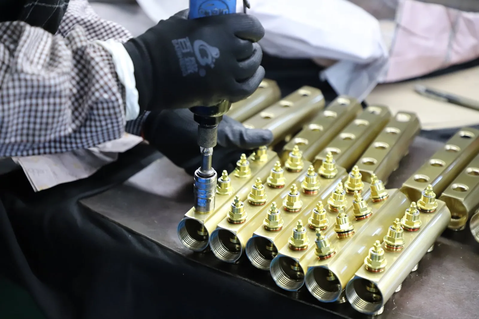
Some of what determines whether an installation goes smoothly is decided before the box is opened. Hitze’s documented in-house quality sequence pressure-tests pipes, fittings and joint assemblies on hydrostatic benches against DIN and EN ISO thresholds, and stainless manifold sets ship assembled on their brackets, pressure-tested and boxed as working assemblies. That is the same class of production proof described earlier in this guide, where published manufacturer data puts the post-assembly test at 6 bar at 20 °C under DIN EN 1264-4.
What it means practically is that a set arriving on site should already be square, complete and leak-free — so a leak discovered at first fill is far more likely to be a Eurocone assembly made on site than a factory joint. When you request the torque figure for your set, ask for the test record alongside it; both are documents a supplier either has or does not.
The figures worth checking on any manifold submittal are the ones that bound what you can do with it. Hitze publishes a working pressure of up to 6 bar and a working temperature of up to 80 °C, a 1″ body up to four ports rising to 1¼″ from eight ports, ¾″ Eurocone loop outlets, M30 × 1.5 actuator ports in 24 V or 230 V, and flow meters graduated 0–2.5 L/min.
Those six numbers are what an installer actually collides with: the 6 bar sets the ceiling of your DIN 18380 test, the 0–2.5 L/min sets whether your design flow rates are even readable on the gauge, and the M30 × 1.5 decides whether the actuators already in your van will fit. A supplier who cannot give you those six on request is a supplier whose manifold you cannot size a test or a control strategy around.
On material, the grade is the specification. Hitze stainless bodies are AISI 304 / EN 1.4301 with 316 / 1.4401 available on request for aggressive or high-chloride water, and an EN 10204 3.1 material certificate is issued for the body material. That 3.1 certificate is the one that matters on a specified project, because it is issued by the manufacturer’s authorised inspection representative against the actual material — it is the document a specifier can hold against a submittal, rather than a general statement of conformity.
On the credentials themselves, the honest position is a scope statement rather than a serial number. Hitze holds credentials including cUPC/UPC, NSF/ANSI 61, DVGW, WRAS and CE with DoP across applicable ranges, and certificate numbers are available on request.
Do not accept — from any supplier — a logo on a brochure as proof that a specific model is covered. Ask which certificate covers which model, and check the covered scope and current validity yourself; the certifications and compliance page is the starting point for that request. Requirements vary by market and by the importer’s role, so confirm what your jurisdiction actually needs before committing to a range.
The system-level point is oxygen. A manifold made of steel and brass sits in a closed loop with residual dissolved oxygen and constant thermal cycling, and ordinary polyethylene lets oxygen diffuse straight through the pipe wall. That is what DIN 4726 exists to prevent, and why Hitze UFH coils carry an EVOH barrier to it. Pairing a barrier-free pipe with a metal manifold is a corrosion programme with a delayed start — our article on the DIN 4726 oxygen barrier covers the mechanism.
Is this installation route right for your job?
This guide describes a wet, embedded, screeded hydronic installation with a metered manifold — the mainstream European radiant floor. It is not universal, and a fair amount of grief comes from applying its sequence to a job it does not fit. The pressure-test-then-pour logic assumes there is a pour. The 21-day cement wait assumes a traditional screed. Neither applies to a retrofit low-profile overlay or a dry system on battens, where the manufacturer’s own build-up instructions govern and the timings are entirely different.
| Best fit for this sequence | Not the right guide for |
|---|---|
| New-build screeded floors, cement or anhydrite | Electric mat systems — no manifold, no hydronics |
| Multi-zone homes and light commercial, 2–12 loops | Single-loop bathrooms fed off a radiator circuit |
| Boiler or heat-pump fed loops with per-loop metering | Low-profile retrofit overlays and dry battened systems |
| Contractors who must sign a test and handover protocol | DIY installs without a heat-loss design behind them |
One honest limitation belongs here too. Without a room-by-room heat-loss calculation, none of the numbers in this guide produce a working floor — they produce a floor that is plumbed correctly and sized by guesswork. The loop-length rules of thumb, the port counts, the flow rates: each of them is downstream of a design. If a job arrives with no heat-loss figures, the correct move is to get them done, not to pick a spacing that looks about right.
Worked example: a seven-loop ground floor from delivery to handover
Take an illustrative ground floor of roughly 115 m² heated area, cement screed, boiler-fed, designed at 150 mm spacing in 16 × 2.0 mm barrier pipe. At the Hitze rule of thumb of about 15–20 m² per loop, that lands at seven loops, so the specification is an eight-port manifold — seven loops connected and one port spare, which is a habit worth keeping because a spare port is the cheapest future-proofing available. At eight ports the body is 1¼″, so the primary flow and return into the plant room are sized to that, not to the 1″ body a four-port job would have used.
Pipe comes off 200 m coils in 16 × 2.0 mm, so each 200 m coil yields two loops of roughly 100 m with the tails included, and four coils cover the seven loops with material left over. Nothing is jointed under the floor. Loops are set out, tagged at the manifold with their reference and design flow rate, and connected to the ¾″ Eurocone ports — nut, olive, insert, in that order, each pipe end cut square and deburred, tightened to the figure on the manifold instruction sheet.
Fill runs from mains through the flow fill/drain valve with both isolation valves shut, one circuit at a time, each purged until the discharge runs clear. The strength test then goes on at 6 bar — the top of the DIN 18380 band and the top of the manifold’s 6 bar working rating — held 60 minutes on a gauge that resolves 0.1 bar, and the protocol is signed by the heating contractor and the main contractor before the screeder is let anywhere near the floor. The pressure stays on for the pour.
Screed goes down at 45 mm cover above the pipe, in a shell held above 5 °C, with the edging strip fixed to give the slab its 5 mm of movement, sleeves where two loops cross the door-jamb expansion joint, and three moisture measuring points marked and kept clear of pipework.
Then nothing happens for 21 days.
On day 22 functional heating starts: 25 °C for three days, then maximum design flow temperature for four more, running continuously overnight, logged by date and temperature. On day 29 the system is proven — and the floor is still not necessarily dry. The flooring contractor takes CM readings at the marked points and works to 1.8% for the cement screed, and if the readings are high, a drying regime gets ordered as separate work. The handover pack goes out with the as-built layout, the port schedule, the achieved flow rates, the signed test protocol, the heating log and the moisture readings.
The instructive part of that timeline is how much of it is waiting. From screed pour to a proven system is a minimum of 28 days on cement, and no amount of site pressure changes it. Programmes that assume a fortnight are programmes that will either fire the loops early and crack the floor, or lay flooring over wet screed. If you are sizing pipe against loop lengths for a job like this, the multilayer pipe sizing guide sets out the flow and pressure behaviour across 16 to 32 mm.
Frequently asked questions
What pressure should an underfloor heating system be tested at?
For heating systems, the DIN 18380 strength test is cold water at minimum 4 to maximum 6 bar, held 60 minutes with no drop. The 11 bar / 30 minute figure is DIN EN 806-4 potable pipework, not a 6 bar manifold.
Can I leave the loops depressurised while the screed is poured?
No. KAN-therm specifies a minimum of 3 bar during screed laying with 6 bar recommended, and Uponor requires the pipes to be under operating pressure. A pressurised loop reveals a puncture while the pipe is still reachable.
How tight should a Eurocone loop nut be?
There is no standard figure. EN 16313:2013 standardises the Eurocone’s geometry only, not tightening force, so the correct torque varies with olive, insert and body material. Use your manifold manufacturer’s instruction sheet.
Are actuators from a different brand compatible with the manifold?
Usually yes where both use the M30 × 1.5 return-port thread, which Hitze and most modern manifolds share. Confirm the voltage matches your wiring centre, since 24 V and 230 V are both common, and check pin travel.
Does functional heating dry the screed enough to lay flooring?
No. Functional heating is a function test under VOB / DIN 18380, and drying to laying maturity is a separate operation that must be ordered separately. Confirm readiness with a CM measurement, not with elapsed heating days.
Can the underfloor system be filled from the boiler filling loop?
No. Commissioning instructions specifically warn against it. The filling loop cannot generate the velocity needed to carry air out of a 100 m circuit, so fill from mains through the manifold fill and drain valves instead, one loop at a time.
What if the pressure test period will run through frost?
Switch to the ZVSHK air or inert-gas route: tightness at 150 mbar for at least 120 minutes per 100 litres of pipe volume, then strength at maximum 3 bar for 10 minutes. Undrained water splits pipework.
Conclusion
Underfloor heating manifold installation rewards discipline in sequence far more than skill at any individual joint. Position and port count get fixed against a heat-loss design, loops get connected and labelled before anything is buried, the right pressure test gets held and signed before the screed arrives and stays on through the pour, and the screed gets its full curing period before functional heating begins.
The two numbers most often improvised are the Eurocone torque and the test pressure, and both have documented answers. There is no standard torque, because EN 16313 harmonised the connection’s geometry and never covered tightening force — so that figure comes off your manifold’s instruction sheet or it is a guess. The factory proof pressure is published: 6 bar at 20 °C on the manufacturer data cited above, the same ceiling the DIN 18380 site test works to, against an operating pressure under half that. Both belong in a document rather than in memory.
If you are specifying manifolds for a stocking range or a project rather than buying one off the shelf, the decisions worth settling early are port count against loop count, body size against total flow, and whether the actuator voltage matches your wiring centre. Ask your supplier for the installation instruction sheet and the material certificate at enquiry stage, so both are in hand before the first set ships.
Sources and further reading
- BSI — BS EN 1264-4:2021, Water based surface embedded heating and cooling systems: Installation
- Uponor — Underfloor heating and cooling planning information (screed cover, edge joints, expansion-joint sleeves, functional heating)
- KAN-therm — Surface heating and cooling guidebook (circuit lengths, screed pressure, heating protocol, CM limits)
- Fränkische — Pressure test guide and test-report templates (DIN 18380, DIN EN 806-4, ZVSHK air test)
- Underfloor Heating Systems Ltd — Filling and commissioning instructions
- ISO 21003-1:2008 — Multilayer piping systems for hot and cold water installations inside buildings


