Key Takeaways
- A cold room with the pump running is almost never a dead pump. It is water short-circuiting through the shortest loops while the longest loop starves. Balancing fixes it at the manifold, not in the plant room.
- Every loop gets a calculated target, not a guess: flow (L/s) = heat output (kW) ÷ (ΔT × 4.18). A 1 kW loop at a 7 K design ΔT needs about 0.034 kg/s — roughly 2.0 L/min on the sight gauge.
- Open the longest, highest-load loop fully and throttle every other loop down relative to it. Throttling the index loop just forces the pump to work against resistance you added for nothing.
- Balance with actuators off or held open. Thermoelectric actuators are normally closed with no power — balancing against closed valves gives you zero-flow readings and a wasted afternoon.
- Purge loop by loop at mains pressure before you trust any flow meter. Air in the sight gauge makes the float bounce and lie.
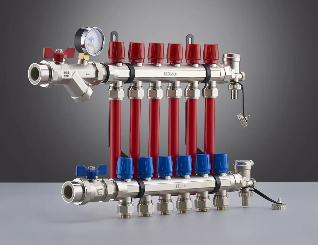
The callback usually lands in the first cold week of the season: the pump hums, the boiler or heat pump cycles, five rooms are warm — and the big living room at the far end of the house never gets above 17°C. The homeowner has already decided the system is broken. You know better: the system is unbalanced. Water is lazy. Given seven parallel loops of different lengths, it will pile through the short bathroom loop at 30 kPa of loop resistance and send a trickle through the 95 m living-room loop. Balancing an underfloor heating manifold is the procedure that forces each loop to take exactly the flow its room needs — and the flow meters on the manifold bar are the only honest witnesses you have. This guide is the commissioning procedure, start to finish, with the arithmetic worked out. If you are still choosing the manifold itself, that decision — brass versus stainless, port count, meter scales — is covered separately in our manifold selection and sizing guide; this article assumes the hardware is on the wall and the loops are connected.
Why one cold room means an unbalanced manifold, not a dead pump
Parallel hydraulic circuits share flow in inverse proportion to their resistance. A 60 m bathroom loop might present half the pressure drop of a 95 m living-room loop, so it takes roughly double the flow — even though the bathroom needs a fraction of the heat. Left unbalanced, the short loops run at a tiny ΔT (water racing through, barely cooling), while the long loop runs at a ΔT of 15 K or more: whatever water does creep through gives up all its heat in the first third of the coil and the far end of the room stays cold. The pump sees a system that looks fine. The flow meters tell the truth: on an unbalanced manifold you will typically see the short loops pinned high on the scale and the index loop hovering near zero.
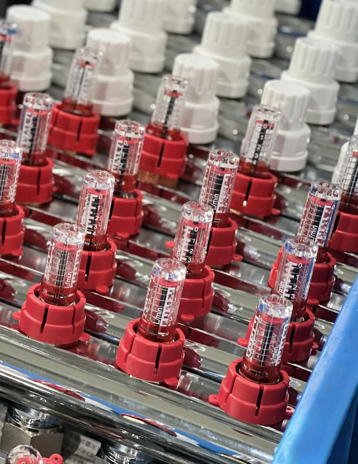
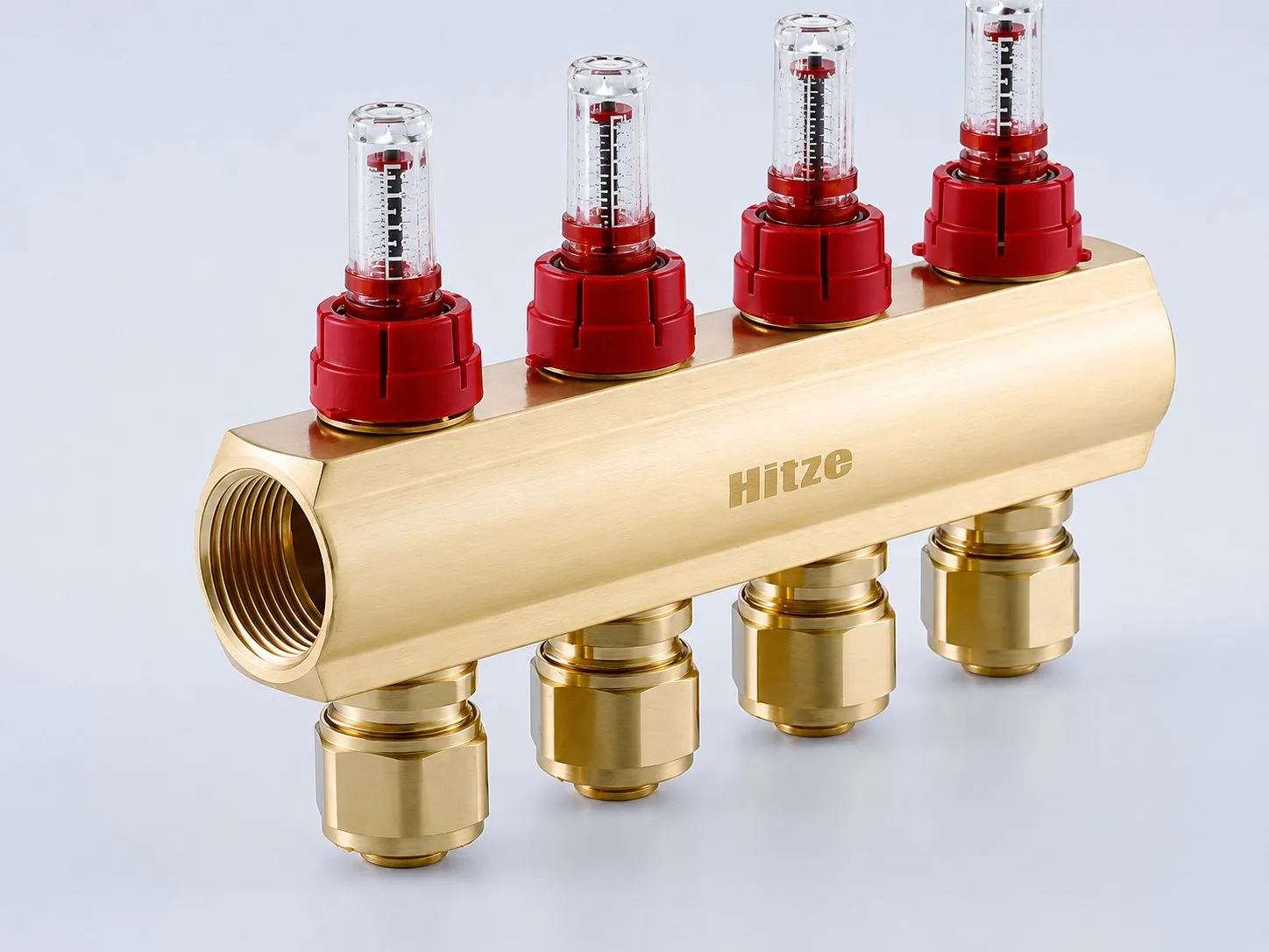
This is why the sight gauge matters more than any other component during commissioning. Hitze manifold flow bars carry clear sight-gauge flow meters graduated 0–2.5 L/min per loop — a deliberately fine scale, because most residential loops land between 0.6 and 2.1 L/min, and a fine scale lets you resolve a 0.2 L/min adjustment by eye. A coarser 0–4 or 1–5 L/min gauge compresses the entire residential working range into the bottom third of the tube; a 0.2 L/min error there is a needle-width you cannot see. The trade-off is honest: on a 0–2.5 scale a very high-flow loop (a large open-plan zone designed at a tight 5 K ΔT) can peg the meter — the correct response is to split that area into two loops at design stage, which the arithmetic below will flag before you ever reach the wall.
One insider diagnostic before you touch anything: feel the return bar port by port after 30 minutes of running. Hot return on a short loop plus a stone-cold return on the long loop is unbalance. Cold flow and cold return on one loop while its meter reads zero, with the loop valve open, usually means an airlock — a different problem with a different fix, covered in Step 2. Diagnose before adjusting; turning meters against an airlock teaches you nothing.
Step 1 — Put a calculated target on every loop
Balancing without targets is just moving the problem between rooms. The target flow for each loop comes from two numbers you already have from the heat-loss design: the loop’s heat output and the system design ΔT (flow temperature minus return temperature). The formula, as published in radiant design guidance such as the H2X underfloor heating design guide, is:
Flow (L/s) = Heat output (kW) ÷ (ΔT × 4.18)
The 4.18 is the specific heat of water in kJ/(kg·K); with water at roughly 1 kg per litre, litres per second and kilograms per second are interchangeable for this job. Worked through for a loop carrying 1 kW at a design ΔT of 7 K: 1 ÷ (7 × 4.18) = 0.0342 kg/s. Multiply by 60 and you get 2.05 L/min — call it 2.0 on the gauge. That single line of arithmetic is the whole intellectual content of balancing; everything after it is plumbing. European design ΔT for underfloor systems typically sits at 5–10 K, and formal dimensioning of embedded systems is the territory of EN 1264-3, the European dimensioning standard for water-based surface embedded heating — if the job came with an EN 1264 design pack, the per-loop flows are already printed in it and you should use those numbers, not recompute your own.
Here is the formula pre-computed across the realistic residential range, so you can see how ΔT choice moves the gauge reading:
| Loop heat load | ΔT 5 K | ΔT 7 K | ΔT 10 K |
|---|---|---|---|
| 0.4 kW | 1.1 L/min | 0.8 L/min | 0.6 L/min |
| 0.5 kW | 1.4 L/min | 1.0 L/min | 0.7 L/min |
| 0.6 kW | 1.7 L/min | 1.2 L/min | 0.9 L/min |
| 0.8 kW | 2.3 L/min | 1.6 L/min | 1.1 L/min |
| 1.0 kW | 2.9 L/min — over a 2.5 gauge | 2.1 L/min | 1.4 L/min |
| 1.2 kW | 3.4 L/min — split the loop | 2.5 L/min | 1.7 L/min |
Read the bottom-left corner of that table carefully, because it hides the most common heat-pump-era design error. Heat pumps favour tight ΔTs of around 5 K for efficiency, and a tight ΔT roughly doubles the flow a loop needs compared with a 10 K radiator-style mindset. A 1.2 kW open-plan loop at ΔT 5 K wants 3.4 L/min — past the top of a 0–2.5 L/min meter and, in 16 mm pipe, pushing toward the roughly 1 m/s velocity ceiling that radiant design guides commonly cite for noise and pressure-drop reasons. The fix is never “wind the meter past max”; it is splitting the area into two loops of 0.6 kW each at a civilised 1.7 L/min apiece. The pipe you laid also sets the resistance the meter is fighting — loop length conventions (typically up to about 100 m for 16 mm pipe) and the material’s bend behaviour differ between pipe families, which we compare in detail in PE-RT vs PEX for underfloor heating.
Step 2 — Purge every loop before you trust a single reading
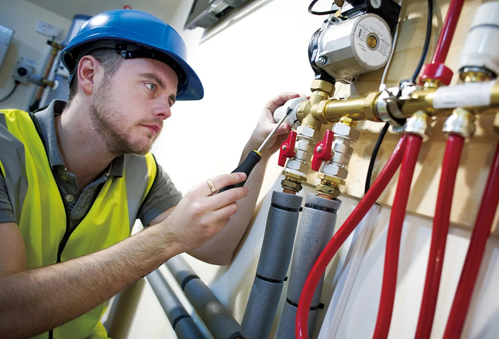
Air is the enemy of both heat transfer and honest metering. A sight-gauge float in aerated water bounces, sticks, and reads high or low at random — you can spend an hour “balancing” readings that were fiction. Worse, the circulator cannot purge a floor system on its own: at radiant flow velocities, bubbles in a horizontal coil under a screed simply will not be swept back to an air vent. The purge has to be done loop by loop, at mains or filling-loop pressure, before balancing starts.
The procedure that works: close the isolation valves on both manifold bars so the boiler/heat-pump circuit is out of play. Connect a hose from the fill point to the flow bar’s fill/drain valve and a second hose from the return bar’s drain to a bucket or gully. Close every loop except one — meters shut on the flow bar, valves shut on the return bar. Open the fill and flush that single loop until the discharge hose runs glass-clear with no spitting, which on a 90 m loop typically takes a few minutes; cloudy or pulsing discharge means keep going. Close it, open the next, repeat down the bar. Doing loops one at a time matters because an open parallel path lets the flush water bypass the loop that actually holds the air pocket. Finish by pressurising the system and checking the manifold’s gauge holds — a pressure test at this stage catches a weeping Eurocone connection before the screed conversation gets expensive.
One warning worth its own paragraph: if the loops were laid in non-barrier pipe, purging clear water today does not keep it clear. Oxygen diffusing through the pipe wall breeds magnetite sludge that will coat the inside of your sight gauges within a couple of seasons and turn every future balancing visit into a cleaning job first. Barrier pipe to DIN 4726 exists precisely to stop this — the mechanism and the permeability limits are explained in our guide to DIN 4726 oxygen barriers for radiant pipe. If you are commissioning someone else’s non-barrier installation, quote for an inhibitor dose and a stainless manifold, and say why in writing.
Step 3 — Set the meters: longest loop wide open, everything else throttled to target
Now the actual balancing, and the one principle that separates a clean commission from an afternoon of chasing: the index loop — the longest, highest-resistance loop — stays fully open, and every other loop is throttled down relative to it. The logic is pure hydraulics. The pump must overcome the resistance of the worst loop no matter what; every quarter-turn you close on that loop is head the pump has to add across the entire system, which drives up electrical consumption and velocity noise everywhere while gaining you nothing. Balancing means adding resistance to the loops that have too little, never to the loop that already has the most.
With the pump running at its expected duty speed and all loop valves open, work down the bar: identify the loop whose meter reads furthest below target (usually the index loop — leave it alone), then throttle the over-reading short loops toward their targets. On Hitze flow bars the meter body doubles as the balancing valve — turn the graduated body until the float sits on the target line. Expect interaction: closing loop 3 pushes extra flow into loops 1, 2 and 4, so readings you set five minutes ago drift upward. This is normal. Two or three passes down the bar converge to within about 0.1–0.2 L/min of target on every gauge, which is as good as floor heating ever needs. Chasing the last 0.05 L/min is gauge-reading theatre.
If after full convergence the index loop still cannot reach its target with its meter wide open, the manifold is not the problem — the pump setting is. On a fixed-speed circulator, step up a speed. On a modulating pump, raise the constant-pressure or proportional-pressure setpoint one increment and re-check. Resist the reflex to solve a pump-curve shortfall by strangling the short loops to near zero: you will hit velocity noise in their tails and the total system flow will still be short. And if the whole bar reads high and the heat source is short-cycling, the pump is oversized for the duty — turn it down before touching a meter. The pump curve and the meter settings are one system; adjusting one while ignoring the other is the single most common reason a “balanced” floor gets rebalanced three times. This interplay between meter scale, port count and pump duty is also why manifold selection matters upstream — the port-by-port build options are on the Hitze underfloor heating manifold product page, from 2-port bars to 12-port assemblies in brass and brushed stainless.
Actuators: balance with them open, or don’t bother balancing
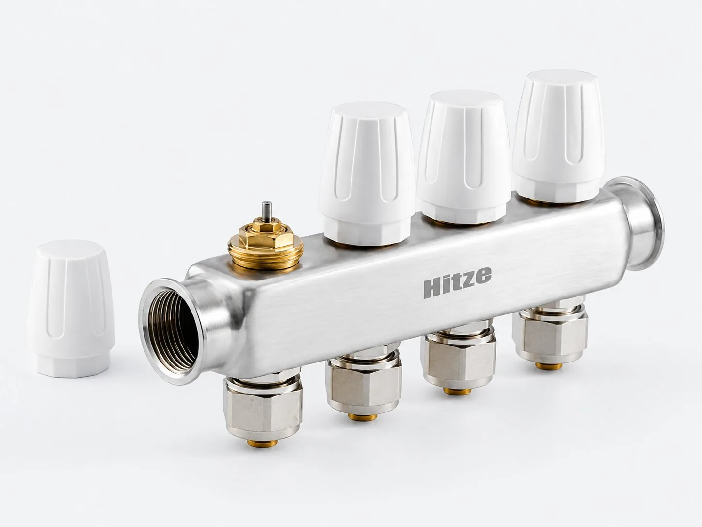
Hitze manifolds ship with white protective caps on the return-bar valves; the M30 × 1.5 valve thread underneath is where zone actuators mount at commissioning. Here is the trap: nearly all thermoelectric actuators used on floor manifolds are normally closed — a typical unit such as the Danfoss Thermot (M30 × 1.5, NC, 230 V, 2 W) holds its valve shut whenever it is unpowered. Fit the actuators first, forget to power the zone wiring, and every return valve on the bar is closed. Every flow meter reads zero. We have seen installers condemn a brand-new manifold on exactly this symptom.
Three clean ways to sequence it. First, and simplest: balance before fitting the actuators — with the factory caps removed or backed off, the return valves sit fully open and the meters read true. Second: use the “first-open” feature that most quality actuators ship with — a clip or tab that mechanically holds the valve open until the first sustained power-up, precisely so heads can be fitted before the controls are wired. Third: power all zones on at the thermostat during the balancing session. Whichever you choose, the rule is absolute — every loop valve must be fully open while you set flows, because a half-stroked valve adds unmeasured resistance that invalidates the reading the moment the valve state changes.
A second-order point that separates careful commissioning from adequate: once zoning is live, actuators will close loops in normal operation, and the flow in the remaining open loops will rise above your set values — a two-open-loop condition on a seven-loop bar can push each open meter noticeably up its scale. That is expected and harmless with a proportional-pressure pump, which sheds head as loops close. With a fixed-speed pump it produces velocity noise on mild days when only one zone calls; if the homeowner reports “ticking pipes in spring,” that is your diagnosis, and the fix lives at the pump, not the meters.
The five mistakes that undo a good balance
Every one of these comes from a real callback pattern, and every one is avoidable in under a minute:
| Mistake | What you see | The fix |
|---|---|---|
| Balancing with unpowered NC actuators fitted | All meters at zero, pump running | Remove heads or use first-open clips; balance valves-open |
| Throttling the index loop | Pump maxed, far room still cold | Longest loop fully open, always |
| Ignoring the pump curve | Index loop can’t reach target, meter wide open | Raise pump speed/setpoint, then re-pass the bar |
| Balancing on aerated loops | Floats bouncing, readings drift day to day | Loop-by-loop mains-pressure purge first |
| Using flow meters as shut-off valves | Meter bodies seized or weeping at next visit | Isolate with the bar valves; meters only trim flow |
| Judging results on day one over wet screed | Rooms lag, owner demands re-adjustment | Let the slab reach steady state before re-touching meters |
The last row deserves expansion because it costs the most goodwill. A heated screed is a thermal flywheel: after first startup, a thick slab can take the better part of a day to reach steady state, and a room’s air temperature lags the water-side settings far behind anything you do at the manifold. Installers who rebalance on day one — because the lounge “isn’t responding” — are correcting a system that hadn’t finished charging. Set the calculated flows, document them, and refuse to touch the meters again until the slab has soaked. The one adjustment worth making early is at the mixing unit or heat source if return temperatures show the design ΔT is far off; the loop-to-loop proportions you calculated remain correct regardless, which is the quiet elegance of balancing by arithmetic instead of by feel.
What Hitze checks before a manifold bar ships
A balancing procedure is only as trustworthy as the hardware carrying it out, so it is worth knowing what sits behind the sight glass. Hitze — a German brand of engineered piping systems, founded in 1974, producing across a 120,000 m² base with 1,000+ employees and exports to 118+ countries — machines its manifold bodies from CW617N brass, with the grade and DN25 size cast directly into the body where an inspector (or a sceptical contractor) can read it. The brushed-stainless bars are built off the same interface set: 0–2.5 L/min sight-gauge flow meters on the flow bar, thermostatic valve seats under white protective caps on the return bar, ready for M30 × 1.5 actuators.
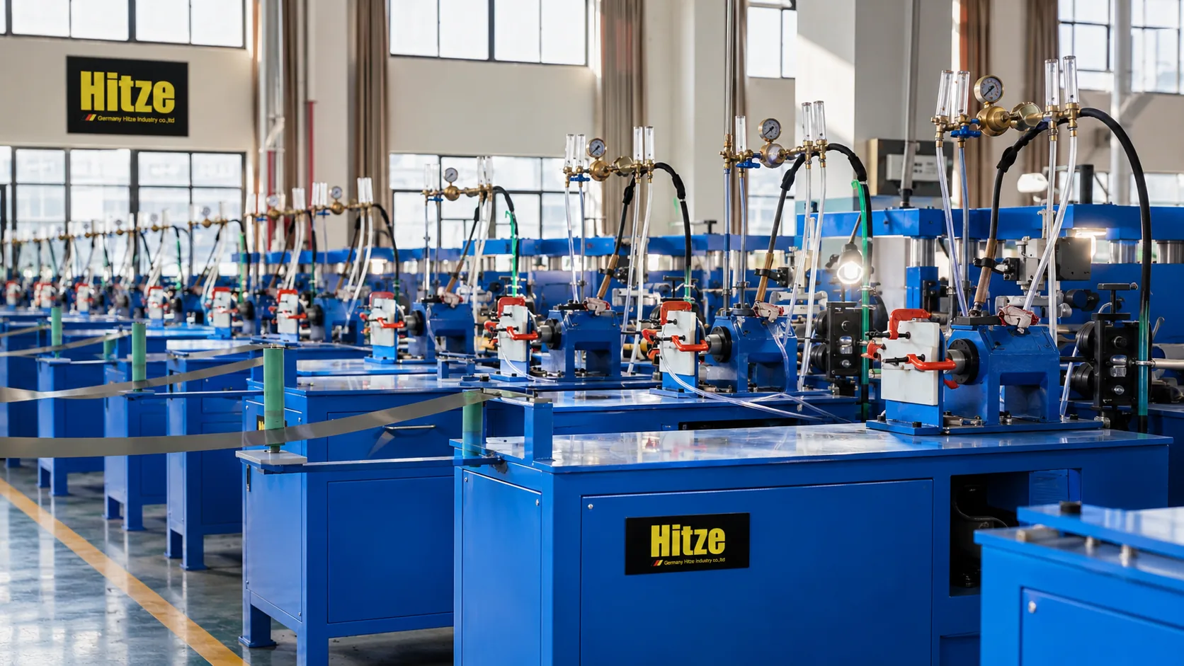
Before dispatch, assembled bars go across dedicated pressure-test benches — gauge, regulator and clamp stations that verify each assembly holds pressure through every meter body, valve seat and end fitting, because a manifold that weeps at a meter O-ring turns a one-visit commission into two. The brass workshop and CNC halls that machine the bodies run under an ISO 45001-certified occupational health and safety management system, and the manifold range is designed to pair with Hitze’s own DIN 4726 barrier PE-RT and PEX heating pipe, so the loop, the Eurocone connection and the bar come from one accountable source. Manifold-specific PN ratings and test-pressure certificates are available on request with the technical pack.
Worked end to end: a seven-loop ground floor, from heat loss to gauge settings
Here is the whole method on one real-shaped job: a 68 m² ground floor on a heat pump, design flow 40°C, design ΔT 7 K, 16 mm barrier pipe, seven loops on one manifold. The heat-loss design gives per-room loads; the arithmetic gives the gauge settings before you ever open a toolbox:
- Living room, 26 m² at 70 W/m² = 1.82 kW. As one loop at 150 mm spacing that is ~173 m of pipe and 3.7 L/min — impossible on both counts. Split into two loops of 13 m²: ~87 m of coverage plus tails ≈ 95 m each, 0.91 kW each → 1.9 L/min per loop. These are the index loops: meters fully open.
- Kitchen, 12 m² at 70 W/m² = 0.84 kW → 0.84 × 60 ÷ (4.18 × 7) = 1.7 L/min.
- Bathroom, 6 m² at 90 W/m² (tile floor, 100 mm spacing, ~60 m loop) = 0.54 kW → 1.1 L/min.
- Home office, 10 m² at 50 W/m² = 0.50 kW → 1.0 L/min.
- Hall, 8 m² at 60 W/m² = 0.48 kW → 1.0 L/min.
- Utility, 6 m² at 50 W/m² = 0.30 kW → 0.6 L/min.
Total: 4.48 kW and 9.2 L/min (≈0.55 m³/h) through the bar — a sanity check the pump datasheet must clear at the system’s design head. On site: purge all seven loops individually until clear, pressure-test, run the pump, confirm the two living-room meters can reach 1.9 L/min wide open (if not, pump setting up one step), then throttle the kitchen to 1.7, bathroom to 1.1, office and hall to 1.0, utility to 0.6. Second pass: the throttling will have pushed the living-room gauges up — they are open-stop loops, so simply re-trim the five throttled loops back to target. Third pass to confirm everything sits within 0.1–0.2 L/min. Fit actuators with first-open clips, wire the zones, record the seven settings on a card zip-tied inside the cabinet. Elapsed time after purging: well under an hour — and every reading on that bar now traces back to a heat-loss number rather than a hunch.
If you are a contractor, distributor or brand building a radiant offer and you want manifold bars whose meters you can actually read at 0.2 L/min resolution — with the pipe, Eurocone fittings and actuator-ready valve seats from the same accountable source — Hitze supplies the matched system trade-wide, backed by a 50-year warranty on the matched pipe-and-fitting system. There is no minimum order quantity: start with samples or a small trial order, put a bar on your own commissioning bench, and judge the sight gauges with your own eyes before committing a container. Details and port configurations are on the underfloor heating manifold page.
Frequently asked questions
Why is one room cold when the underfloor heating pump is running?
Almost always loop imbalance: water short-circuits through the shortest, lowest-resistance loops and starves the longest one. Check the flow meters — short loops pinned high and the long loop near zero confirms it. Balance the manifold rather than replacing hardware. If a loop’s meter reads zero with its valve open and its return pipe is cold, suspect an airlock and purge that loop first.
Should all the flow meters on a manifold read the same?
No — equal readings are usually a sign of guesswork, not balance. Each loop’s target comes from its own heat load and the design ΔT: flow (L/s) = kW ÷ (ΔT × 4.18). A big living-room loop might need 2.0 L/min while the utility loop needs 0.6 L/min on the same bar.
Do I balance before or after fitting the actuators?
Before, or with the valves held open. Thermoelectric actuators are typically normally closed when unpowered, so balancing with unwired actuators fitted gives zero-flow readings on every gauge. Use the actuators’ first-open clips or power all zones on if the heads must go on first.
What happens if I throttle the longest loop?
You force the pump to overcome resistance you added for nothing: every other loop then needs re-throttling, pump head and power rise, and velocity noise appears in the short loops. The longest, highest-load loop stays fully open as the reference; all balancing happens on the other loops.
How often does an underfloor heating manifold need rebalancing?
In a clean, air-free system with barrier pipe — essentially never, unless loops are added or room use changes. Drifting readings usually mean air ingress or, on non-barrier pipe, magnetite sludge fouling the meters, which is a system-water problem to fix at its cause, not with the balancing valves.


