Pressing beside an old soldered joint and soldering beside an existing press joint are different operations. Identify the fitting system and work order before choosing a clearance; never use a jaw-spacing or insertion-depth figure as a heat-clearance rule.
In the first operation, the existing heated joint has already cooled. In the second, a torch introduces heat beside a seal that is already installed. A repair plan that swaps these conditions can select the wrong instruction even when every measurement is accurate.
Key takeaways
- Write down which connection already exists and which operation comes next.
- Find the instructions for that exact press system, material and size.
- Keep heat clearance, tool clearance and insertion depth as separate checks.
- Use the manufacturer’s table for the direction of work; a reverse-order table answers a different question.
- Cooling precautions accompany the stated distance; they do not automatically replace it.
- When the system or permissible distance is unknown, stop heat work and resolve the layout or component identification.
First decide which joint already exists
A drawing labelled “press next to solder” leaves out the fact that decides the check. Is the soldered fitting already in place, with the new press connection to be made beside it? Or is the press joint already complete, with soldering still to come? Record the direction in plain language before measuring.
The distinction appears explicitly in the Viega ProPress installation manual. Section 4.4.1 covers using ProPress in line with existing fittings. Section 4.4.2 covers soldering or brazing in line with an existing ProPress fitting. The manual supplies different distances for these situations. Those instructions apply to the named system; they are not universal rules for every product sold as a press fitting.
| Existing connection | Proposed operation | Instruction to find | Verdict |
|---|---|---|---|
| Cooled soldered fitting | Make a press joint | Press beside existing solder | Use that system’s table |
| Cooled brazed fitting | Make a press joint | Press beside existing braze | Use the brazed-joint rule |
| Completed press joint | Solder nearby | Heat beside existing press | Protect the installed seal |
| Completed press joint | Braze nearby | Brazing beside existing press | Do not substitute solder clearance |
| Unidentified fitting | Apply heat nearby | Exact system instructions missing | Stop and identify it |
Source: Viega, ProPress Systems Installation Manual, IM-PP 724607 1125, sections 4.4.1–4.4.2. The matrix organizes the documented operations; it does not approve other systems.
Also separate three physical dimensions. Insertion depth establishes how far the tube enters the fitting. Jaw or ring clearance establishes whether the specified tool can be placed and operated. Heat clearance concerns the nearby operation. Passing one does not demonstrate that the other two have been satisfied. Our guide to insertion-depth marks and fitting windows addresses the seating check separately.
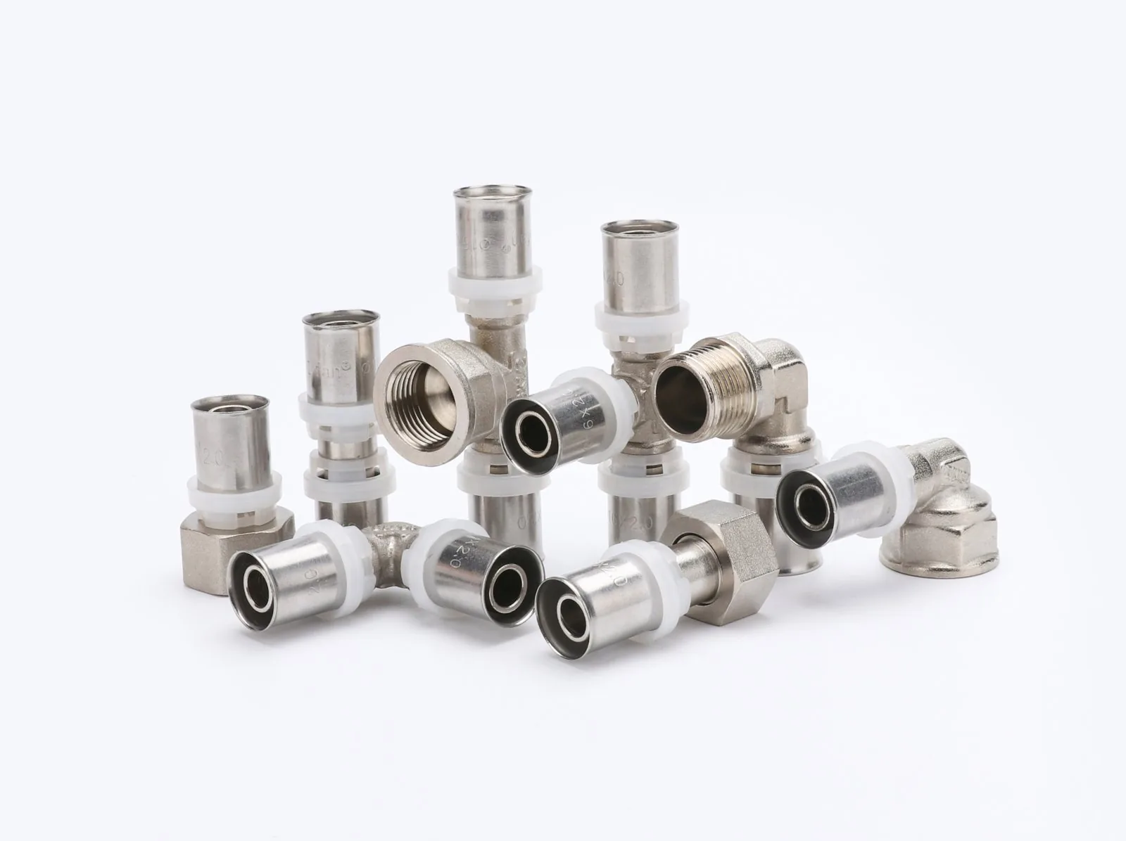
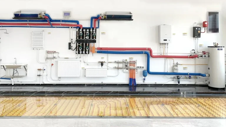
Photo source and scope
Existing Hitze site library, native media 602. Context photograph only; not a ProPress installation, heat-distance demonstration or compatibility approval.
Read the heat-clearance table in the correct direction
Use a named example to see why the distinction matters. For the 1-inch row in the cited ProPress manual, pressing beside an existing soldered fitting has a listed minimum distance of 7/16 inch, shown as 11 mm. Pressing beside an existing brazed fitting has a listed distance of 2 inches, shown as 51 mm. These are the section 4.4.1 conditions.
Now reverse the work. Section 4.4.2 lists 3 tube diameters for soldering beside an existing ProPress connection and 9 tube diameters for brazing. In its 1-inch row, the manual gives 3 inches (76 mm) and 9 inches (229 mm), respectively. Reusing the 11 mm figure for the soldering operation would therefore answer the wrong question.
| Work sequence | Listed distance | Manual location | Use boundary |
|---|---|---|---|
| Press beside old solder | 7/16 in; 11 mm | Table 17 | Exact named system only |
| Press beside old braze | 2 in; 51 mm | Table 17 | Exact named system only |
| Solder beside existing press | 3 in; 76 mm | Table 18 | Include cooling precautions |
| Braze beside existing press | 9 in; 229 mm | Table 18 | Include cooling precautions |
Source: Viega, IM-PP 724607 1125, pages 27–28, Tables 17–18. Inch and millimetre values are reproduced as printed. They are not new unit conversions or Hitze product specifications.
Do not interpolate from this example to another size or transfer it to a multilayer fitting because its sleeve looks similar. Read the applicable row, its surrounding instructions and the manufacturer’s definition or illustration of the measurement. If the measurement endpoints are unclear on the installed geometry, obtain clarification before treating a tape-measure reading as compliant.

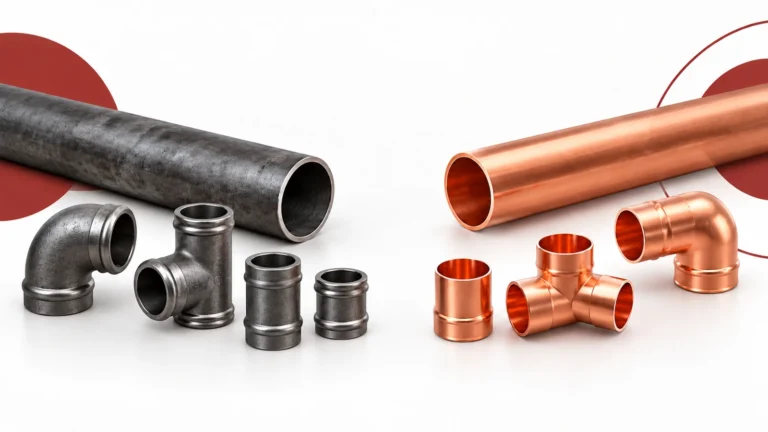
Photo source and scope
Existing Hitze site library, native media 603. Context photograph only; not a ProPress installation, heat-distance demonstration or compatibility approval.
Plan the repair before the torch arrives
The useful outcome is a work sequence that meets the actual instructions. The cited manual lists precautions to keep the ProPress connection cool, including a cold wet rag, a weld blanket, prefabricating soldered connections before installing the press fitting, and heat-sink products. It expressly says the tube must cool before fitting installation in the prefabrication route. These precautions sit alongside its distance instruction.
That gives a contractor a practical planning option: where the approved arrangement allows it, complete the required heat work before installing the heat-sensitive connection. The finished assembly must still meet its joint spacing, clean-tube, support, access and system requirements. Moving heat work earlier does not approve an otherwise incompatible fitting or pipe.
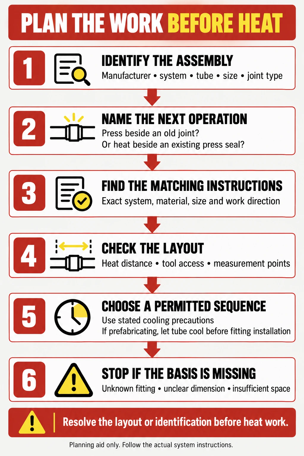
- Identify the assembly. Record the press manufacturer, system, tube material, marked size and nearby joint type.
- Name the next operation. State whether the job adds a press fitting beside an old joint or applies heat beside an existing press connection.
- Select the instruction. Obtain the current installation document for the exact combination and locate the matching operation.
- Check the layout. Confirm the documented distance, tool access and measurement points independently.
- Choose the sequence. Follow the permitted precautions, or arrange compliant prefabrication, a longer spool or a documented alternative connection.
- Stop if the basis is missing. Unidentified components, an unclear dimension or insufficient space require resolution before heat work.

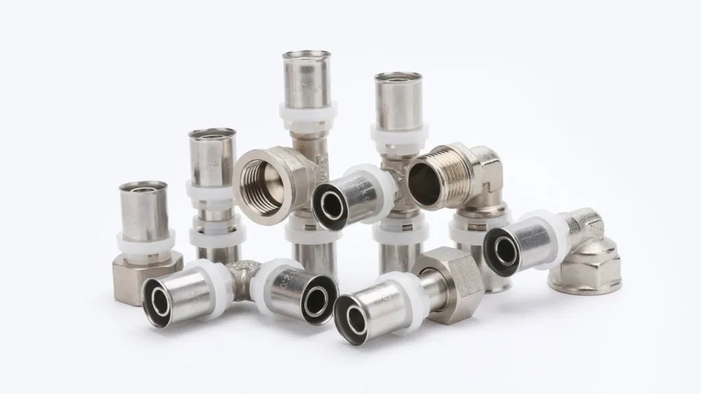
Photo source and scope
Existing Hitze site library, native media 601. Context photograph only; not a ProPress installation, heat-distance demonstration or compatibility approval.
For procurement, specify the connection system before asking for an interchangeable-looking component. The Hitze press-fittings category is a starting point for a component enquiry; it is not evidence that a particular fitting is approved for the Viega distances above. Matching model, pipe, application and installation instructions must be confirmed for the actual proposed assembly.
Submit the specification for an availability check. Include the project country, application, pipe material and size, existing fitting identification, proposed operation and available space. This requests a supply check; it does not establish compatibility, engineering approval, stock or a quoted lead time.
When the joint identity or available space rules out heat
If the required clearance cannot be provided, “use more heat protection” is not a documented solution by itself. A cooling precaution is not permission to shorten a listed minimum. Reconsider the layout: can the affected section be replaced with a longer prefabricated assembly, can the connection be moved, or is an approved mechanical transition available for the exact system and service?
Those are design questions, not automatic substitutions. An alternative must preserve the pipe and fitting compatibility, pressure and temperature suitability, approvals required by the project, access and installation method. Where no documented arrangement fits, stop and refer the connection detail to the responsible designer or system manufacturer. A leak check alone cannot supply the missing installation permission.
The same stop applies when prior heat exposure is suspected but its extent is unknown. A table for planning a new operation cannot establish that an existing seal remains serviceable after undocumented heating. Obtain the relevant manufacturer’s disposition rather than using a short-term leak result to declare the component undamaged.
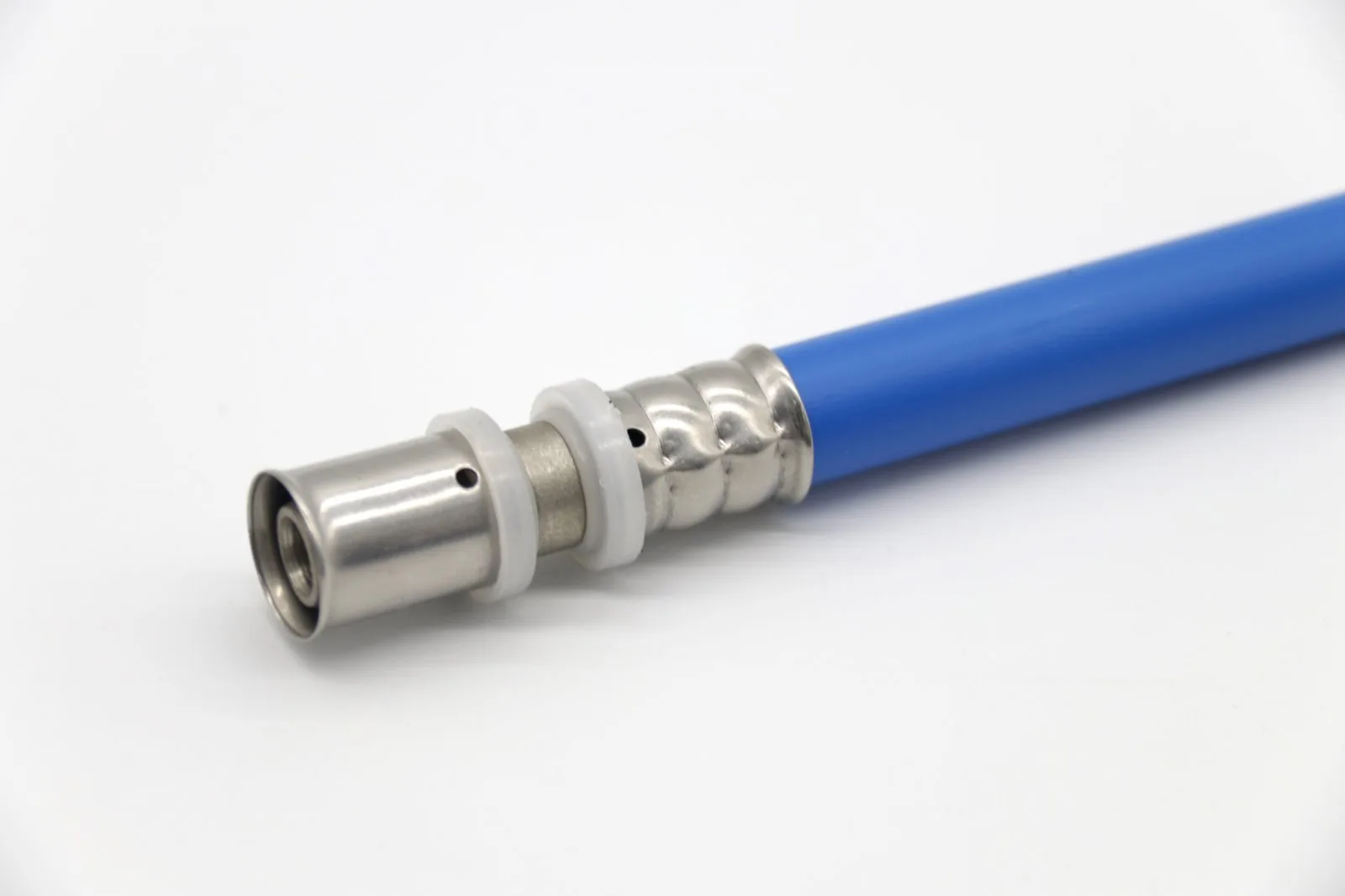
Photo source and scope
Existing Hitze site library, native media 543. Context photograph only; not a ProPress installation, heat-distance demonstration or compatibility approval.
Conclusion
Put the work order on the repair sketch before putting a clearance on it. Identify what already exists, identify the next operation, and use the exact system’s instructions for that direction. If the space or identity does not support the operation, change the connection plan before applying heat.
Frequently asked questions
Does a wet rag let me solder closer to a press fitting?
Do not assume so. The cited ProPress manual lists cooling precautions alongside the stated soldering and brazing distances. It does not make a wet rag a general exemption from them.
Can I use the distance between two press fittings?
That dimension serves a different operation. Use the manufacturer’s specific instruction for pressing beside a soldered or brazed joint, or for applying heat beside an existing press connection.
Can these figures be used for Hitze or multilayer press fittings?
No compatibility conclusion follows from this example. The figures belong to the named ProPress manual and condition. Obtain the applicable instructions for the actual proposed pipe and fitting system.
What should I do if I cannot identify the installed fitting?
Stop the proposed nearby heat work, record the markings and installation detail, and establish the system and applicable instructions. If identification remains unresolved, use a redesigned connection plan approved for the actual service.
Technical source: Viega ProPress Systems Installation Manual, IM-PP 724607 1125, sections 4.4.1–4.4.2. This is a public-source planning guide for trained plumbing professionals, not a site inspection or a Hitze product installation instruction.