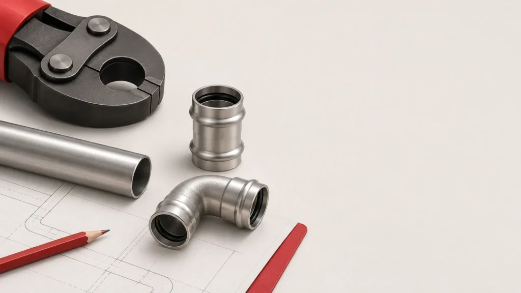
A short press-fitting spool must pass three checks: the specified separation between fitting bodies, the insertion needed at both ends, and the physical space for the approved pressing attachment. A gap that satisfies the fitting table can still leave the jaw trapped against a wall. Check the finished arrangement before cutting the tube.
Key Takeaways
- Choose the exact system/size joint-gap table and its measuring endpoints, rather than borrowing a universal pipe-diameter rule.
- Reconstruct the short tube cut from both insertion depths plus the specified exposed gap; label a worked example as hypothetical.
- Reject a spool where the gap passes but the approved attachment cannot seat/open/close or be removed; review an approved ring alternative or change layout.
- Keep the required insertion at both ends; do not recover space by withdrawing a tube.
- Review tool seating, operation and removal in the final assembly sequence.
Separate joint spacing from tool-access space
Joint spacing and working space have different endpoints. The former measures the separation shown in the fitting-system drawing; the latter describes the envelope occupied by the attachment, drive unit and surrounding construction. Neither is a substitute for the other. An installer may have enough exposed tube between two fittings yet be unable to position the jaw squarely around the pressing location.
Viega separates these subjects in its MegaPress Stainless installation manual, IM-MP 591324 0726, sections 4.3.1–4.3.3. Table 14 addresses fitting separation. Subsequent tables address jaws, nearby pipes and surrounding construction. This is a named-system example of how to read the requirements, not a dimension schedule for Hitze products or copper ProPress.
| Check | Evidence | Failure action |
|---|---|---|
| Fitting separation | Exact series/size gap drawing | Revise exposed gap |
| Insertion | Both required depths and witness marks | Recut; do not withdraw tube |
| Access | Approved attachment envelope and final position | Relocate or verify approved alternative |
Identify the exact fitting and attachment before using a drawing
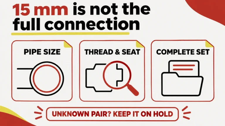
Record the pipe material, fitting series, size and attachment identification on the spool review. A note saying “press fittings” leaves too much unresolved: a drawing for another system can have a different gap, insertion geometry or tool envelope. Even a matching nominal diameter does not establish that the actual tube and fitting belong together.
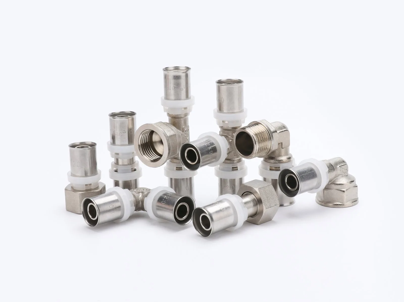
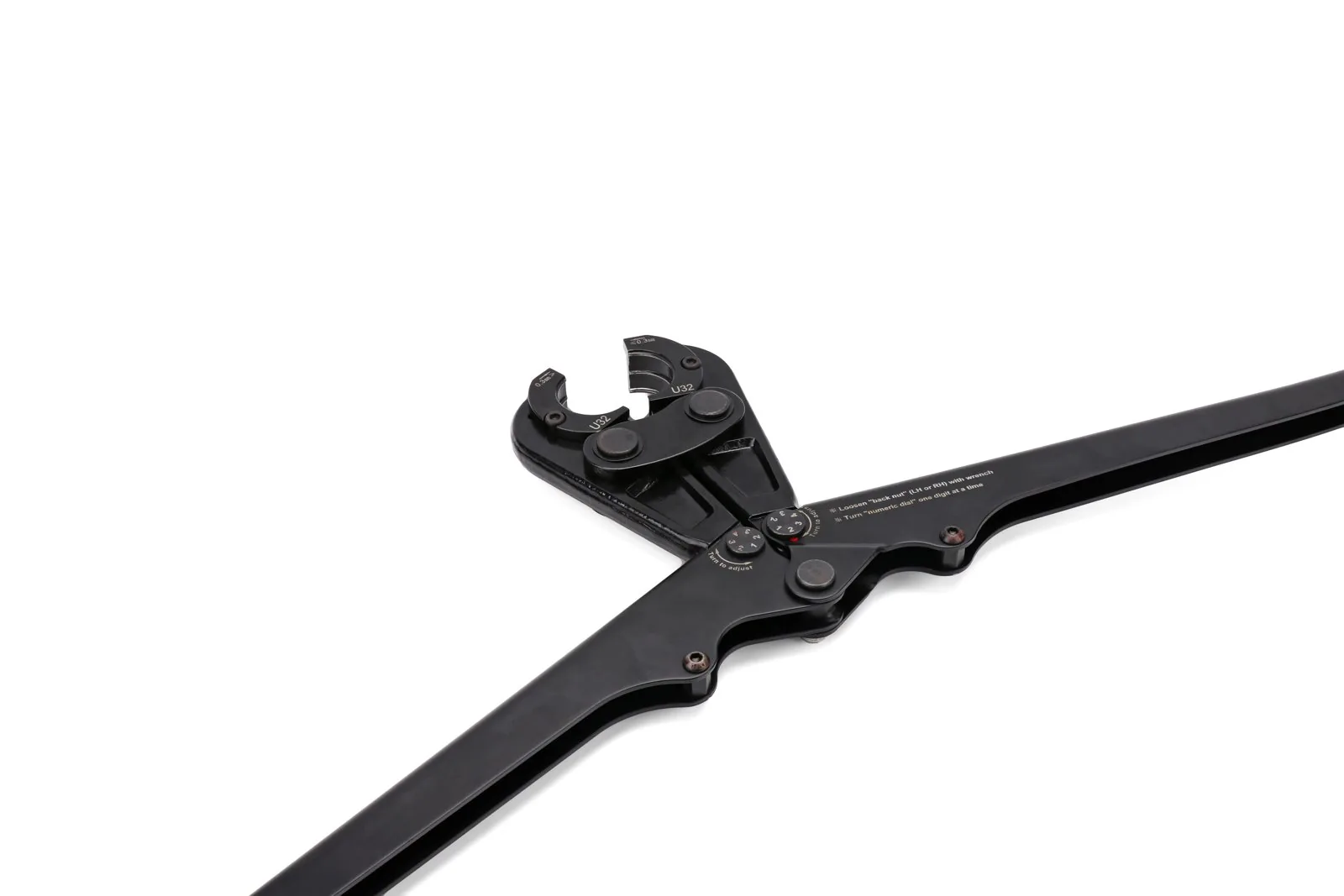
Start with the current fitting instructions, then locate the approved attachment drawing for the actual tool combination. The separate jaw-profile compatibility guide explains that selection boundary. Here the next question is physical: can that approved combination perform the connection at its final location? A profile letter alone cannot answer it.
Calculate the short tube without losing either insertion depth
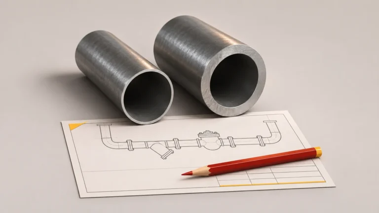
For two ordinary stopped fittings on a straight tube, define dA and dB as their required insertion depths, and g as the exposed tube between the two fitting mouths. With those endpoints, the cut length is L = dA + g + dB. This is a geometric relation, not a universal insertion-depth specification. Obtain each depth and the minimum allowed gap from the exact fittings, rather than estimating the hidden lengths from an outside photograph.
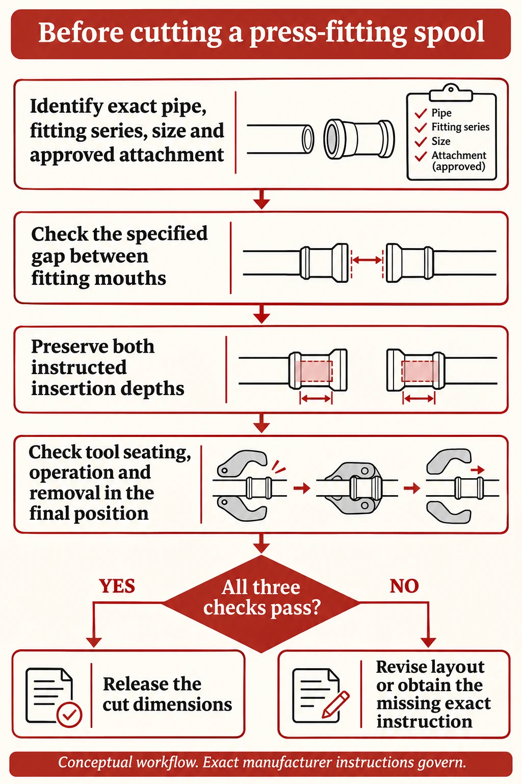
- Identify exact pipe, fitting series, size and approved attachment.
- Check the specified gap between fitting mouths.
- Preserve both instructed insertion depths.
- Check tool seating, operation and removal in the final position.
- If all checks pass, release the cut dimensions; otherwise revise the layout or obtain the missing exact instruction.
For a purely hypothetical calculation, suppose the two instructed depths are 24 mm and 28 mm, and the selected exposed gap is 15 mm. The tube cut would be 67 mm. If that exact system instead requires a gap of at least 20 mm, the proposed 67 mm tube is short: preserving both insertions leaves only 15 mm. The corresponding minimum becomes 72 mm. These invented inputs teach the calculation; they do not identify any product’s dimensions.
Do not rescue the shorter tube by withdrawing one end. That converts a spacing problem into an insertion defect. Verify the installed depths using the system’s marks; the insertion witness-mark article covers that separate check. Sliding no-stop repair couplings need their own minimum/maximum insertion instructions and are outside this simple stopped-fitting example.
| Hypothetical term | Input | Meaning |
|---|---|---|
| dA | 24 mm | Required insertion at end A |
| dB | 28 mm | Required insertion at end B |
| g | 15 mm | Selected exposed gap |
| L | 67 mm | 24 + 15 + 28; geometry only |
Check the installation sequence and the final accessible position
Check the attachment’s route to the fitting, its fully seated pressing position and its route out again. Include the neighboring fitting, pipe supports, wall, ceiling and any object that will already be installed. Access while holding a loose spool in the air is not proof of access once it is fixed in place.

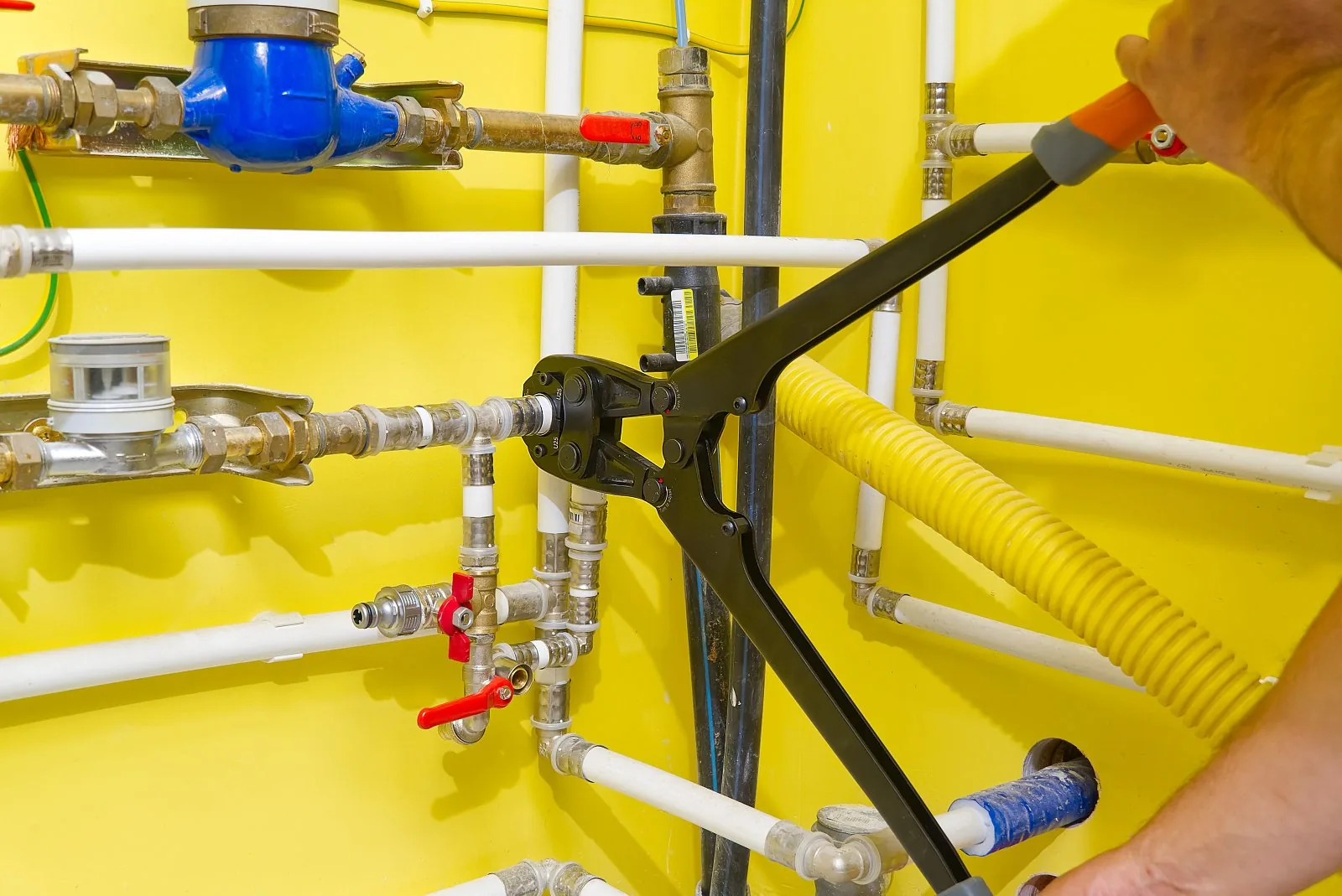
Review both joints in their actual assembly order. Pressing the first may remove movement that made the second seem accessible. A flange, threaded end or fixed support may also constrain the arrangement; follow the exact system’s assembly instructions rather than rotating a completed joint to recover space. Use the manufacturer’s clearance drawing to compare the real arrangement, including the particular jaw or ring. Do not scale a small diagram by eye.
If the listed attachment cannot seat, operate and be removed, record access as failed even when the joint gap passes. An alternative ring or attachment is only a candidate until its approval and its own access requirements are verified. A smaller-looking tool is not automatic permission to substitute.
Decide whether to recut, move the spool or verify an approved attachment
Release the cut only when all three rows of the review agree. If the gap fails, lengthen the exposed section or change the arrangement while preserving both insertions. If the gap passes but access fails, revise the location or verify a specifically approved alternative attachment. If the source drawing is absent, hold the dimension rather than guessing a generous allowance.
For an availability discussion, give Hitze’s press-fitting team the exact pipe/fitting specification, size, drawing and tool constraint. Ask whether a suitable configuration can be supplied; the Viega example above does not establish a matching Hitze SKU or tool approval. A quotation cannot replace the system’s installation evidence.
Conclusion
A cut is ready when joint spacing, both insertions and final tool access pass independently. Keep every dimension attached to the exact system that supplied it.
Frequently Asked Questions
Does a zero minimum gap mean any tool will fit?
No: a joint-gap allowance addresses the fitting separation. The approved attachment still needs its specified operating and removal space.
Can I reduce insertion to gain exposed pipe?
No. Preserve the exact required insertion at both ends and change the cut or arrangement instead.
Does the cut-length equation cover no-stop repair couplings?
Not by itself. Sliding repair couplings have their own insertion range and positioning instructions.
Technical source: Manufacturer instructions. Named-system examples apply only within their documented scope.