You cannot fuse PP-R to HDPE. There is no heated-tool joint, no electrofusion coupler and no socket that will bond the two, and PP-R manufacturer guidance says so in as many words: polypropylene “should never be fused to PVDF, PE, CPVC, or any other type of plastic.” Every connection between a PP-R building circuit and an HDPE service main is a mechanical joint, made through a part that becomes the weakest component in the run.
That leaves three routes: a flange adapter with a loose backing ring, a threaded transition fitting with a metal insert, or a mechanical compression coupling. Which one belongs at your diameter is a decision with acceptance numbers attached, and this guide covers those numbers, the size band each method serves, and what to put to a supplier before the detail is buildable.
Key takeaways
- No fused joint exists. PP and PE are immiscible and do not co-crystallise; HDPE is fully molten below 137 °C, isotactic PP melts between 160 and 175 °C.
- Three legal routes only: compression fittings, flanges, or qualified manufactured transition fittings.
- Flange from about DN63 up, thread below it. ISO 9624 backing-flange dimensions run 16 mm to 2,500 mm, up to PN25.
- The re-torque is not optional. PPI specifies re-tightening about four hours after final torque; PP-R guidance says within 24 to 48 hours.
- One to two turns past hand-tight on a threaded transition. Once the brass insert turns inside the PP-R body, nothing will seal it.
- Put the joint on the cold side. PP-R design stress falls from 6,93 MPa at 20 °C to 2,12 MPa at 70 °C.
On this page
- Why PP-R and HDPE cannot be fused to each other
- The three transitions that are actually permitted
- The flanged transition: stub end, backing ring and what bolts to what
- Bolt torque and the re-torque almost nobody does
- The threaded brass-insert transition and its two failure modes
- Mechanical couplings: where they belong and where they pull out
- Where the transition sits: cold side, supported, restrained
- Testing the transition and what to record
- What to confirm with the supplier before you specify the part
- Frequently asked questions
Bolt pattern and round order lose more flanged joints than the torque figure does. This bolted-joint training clip works a criss-cross sequence and staged rounds on a real flange; treat it as general bolting practice rather than a plastic-flange procedure, because the PE-specific bands and rounds are in the table below.

Why PP-R and HDPE cannot be fused to each other
Both materials fuse beautifully to themselves, which is what makes the mistake tempting. A correct PP-R socket joint is homogeneous, with no O-ring and no seal inside it, and HDPE mains are butt-fused into continuous strings the same way. Put a PP-R iron against an HDPE spigot and you get a joint that looks finished and carries almost nothing.
The reason is chemistry, not technique. Research published in Macromolecules in 2022 describes blends of the two polymers as showing “phase separation with poor interfacial adhesion,” with “poor mechanical properties such as brittleness and low peel and impact strength.” The phases crystallise separately, so no entangled interface forms at the joint line.
The processing windows confirm it. That study records complete HDPE melting below 137 °C while isotactic PP melts between 160 and 175 °C, so no single tool temperature brings both surfaces into a usable melt at once. The welding guidelines split the same way: PP-H, PP-B and PP-R fall under DVS 2207-11, PE-HD under DVS 2207-1, each with its own melt-flow-rate compatibility range.

A cross-polymer joint that survives the hydrostatic test is the dangerous outcome: held by mechanical keying in the cooled interface, invisible to a 10-bar test, and failing later under thermal cycling once the wall is closed. Our guide to plastic pipe fusion welding methods sets out what genuinely can be welded together.
The three transitions that are actually permitted
The PE side sets the menu. The PPI Handbook of PE Pipe states that “PE pipe may be joined to other pipe materials by means of compression fittings, flanges, or other qualified types of manufactured transition fittings.” That sentence is the whole permitted set.

Diameter decides which one, with demountability as the tie-breaker. Below about DN50 the threaded transition is practical: PP-R fittings in that range carry a machined metal insert, and a bolt circle would dominate the part. From about DN63 up the flanged route takes over, because loads are higher and the joint usually has to come apart for a valve or a meter. Hitze’s PP-R range runs OD 20–110 mm (DN15–90), straddling that boundary.
| Size band (OD, mm) | Recommended method | What mates to what | Acceptance check |
|---|---|---|---|
| 20–50 | Threaded transition fitting | PP-R fitting with metal insert, into a threaded PE adaptor | Hand-engages 2–3 turns dry; 1–2 turns past hand-tight; insert must not move |
| 20–63 | Mechanical compression coupling (ISO 14236) | Elastomeric gasket compressed around each pipe end | PE end carries an internal stiffener; joint restrained against end load |
| 63 and above | Flange adapter plus loose backing flange | PP-R flange adapter to PE stub end, bolted through a common drilling | Same declared drilling standard both sides; torque built in rounds; re-torqued |
| Any | Factory transition fitting | Pre-assembled, carrying a short segment of PE pipe to butt-fuse | Manufacturer’s qualification documentation supplied with the part |
Source: permitted methods from PPI Handbook of PE Pipe, ch. 9; compression fittings ISO 14236:2000; backing-flange mating dimensions ISO 9624:2019. Size bands are engineering practice rather than a clause — confirm the range your supplier stocks.
One route is absent on purpose: there is no qualified cross-polymer electrofusion coupler for this pair, and any part offered as one should be refused until its documentation arrives.
The flanged transition: stub end, backing ring and what bolts to what
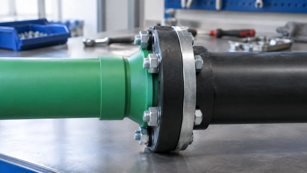
A flanged transition is four parts and one irreversible mistake. On the HDPE side, a stub end butt-fused to the pipe with a loose metal backing ring trapped behind its shoulder; on the PP-R side, a flange adapter socket-fused to the pipe with its own ring. A gasket between them, and bolts through both rings clamping the two plastic faces together.
The mistake is fusing before the ring is on. PPI’s sequence is explicit: “Slip the metal ring onto the PE pipe section… Butt fuse the flange adapter to the PE pipe segment.” Reverse those steps and the only recovery is to cut the joint out. The same applies on the PP-R side.
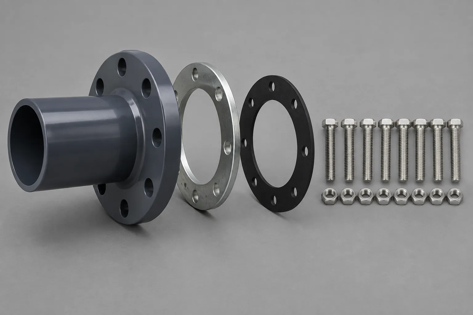
The two rings must share a drilling. ISO 9624:2019 sets mating dimensions for thermoplastic flange adapters and loose backing flanges from 16 mm to 2,500 mm nominal outside diameter at pressures up to 25 bar. What it does not do is choose the drilling standard for you: a ring drilled to EN 1092-1 PN16 will not bolt to one drilled to ASME B16.5 Class 150, and the two halves of a transition are often bought in different markets. Declare the standard on the purchase order.
PP-R manufacturer guidance calls for a full-face rubber gasket, EPDM or SBR, at a minimum 1/8 in. thickness. PPI notes that at “typically 80 psi or less” a serrated sealing surface may be adequate alone; above that, fit the gasket. The backing ring must “carry the applied bolt torque, elastically, without yielding,” which is why a thin plated ring bought on price is a false economy.
Bolt torque and the re-torque almost nobody does
Bolt torque on a plastic flange is computed from a seating stress, not read off a steel-flange chart. PPI TN-38 publishes its bands on a stated basis: non-plated bolts and studs, a nut factor of K=0.16 for lightly greased bolts and nuts, and an HDPE flange face seating stress of 1,200 psi to 1,800 psi.
| Flange pairing | Bolt diameter (in.) | Initial min. lubed torque (ft-lb) | Initial max. lubed torque (ft-lb) |
|---|---|---|---|
| PE to PE, 12 bolts | 0.875 | 105 | 160 |
| PE to steel or ductile iron, 12 bolts | 0.875 | 75 | 114 |
Source: PPI TN-38 (2019), Tables 1, 2 and 3; criss-cross sequence for 12 bolts, 1-7-4-10 >> 2-8-5-11 >> 3-9-6-12. These are polyethylene flange-face values. A PP-R flange face is a different polymer with a different modulus, so ask the PP-R manufacturer for its own seating-stress basis rather than transferring these numbers across.
Build the torque in rounds. TN-38 specifies, for flanges 18 in. and smaller, tightening sequentially to 30% of final torque, returning for 60%, then a final pass to full value; at 20 in. and larger it is four rounds of 25% plus a rotational check. PP-R guidance says the same differently: a third of the torque rating in a star pattern, repeated until fully tightened.
Then wait and do it again. TN-38: “About four hours or so after the first tightening to the target torque value, retighten each bolt’s nut to the final target torque value.” It compensates for seating of the plastic face, bolt creep, nut embedment and gasket compression-set. PPI’s handbook says about an hour; PP-R guidance says within 24 to 48 hours, and again after a seasonal change. Take the longest window the programme allows and record when it was done.
There is a published stop rule worth putting in the method statement: if 150% of the specified torque is reached and the joint still leaks, stop the hydrotest, de-pressurise and disassemble. Chasing a leak with a longer bar crushes the plastic face and turns a re-makeable joint into a replaced spool.
The threaded brass-insert transition and its two failure modes
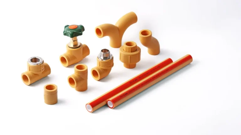
Below roughly DN50 the flange disappears. A PP-R transition fitting is a PP-R body with a machined brass or stainless thread mould-inserted into it: one end socket-fuses to PP-R, the other screws into a threaded PE adaptor. Hitze supplies brass-insert transition fittings within the PP-R fittings range, across the same OD 20–110 mm band as the pipe.
The first failure mode is torque. Manufacturer guidance is to continue “only one or two turns past hand-tight,” never to bottom out, to apply counter-pressure on the fitting body, and never to tighten until the brass insert moves. Once that insert rotates inside the PP-R body the metal-to-plastic seal is broken permanently. A published band for plastic threaded connections puts 10 to 25 ft-lb as adequate, a fraction of what a fitter used to steel applies by feel.

The second is a thread-standard mismatch that feels like a tight fit. ISO 7-1 covers jointing pipe threads in sizes 1/16 to 6 sealed by the threads themselves: R taper external, Rc taper internal, Rp parallel internal, at a 1/16 taper and a 55° flank angle against 60° for NPT. An NPT male driven into an Rp female engages, resists, and seals on tape rather than metal. The dry test is the diagnostic: if the threads do not run in cleanly by hand for two or three turns, that is a mismatch, not a tight fit, and force will not improve it.
Sealant carries its own risk: some pipe joint compounds and PTFE pastes can cause stress cracking in plastic fittings, so use a tape or paste specified for plastic threads. Our guide to connecting PP-R to metal pipe covers thread selection in more depth.
Mechanical couplings: where they belong and where they pull out
A bolted mechanical coupling is the third permitted route and the most misunderstood, and in practice it is a 20–63 mm OD answer rather than a large-diameter one. ISO 14236:2000 governs mechanical-joint compression fittings for polyethylene pressure pipes in water supply systems. PPI describes the mechanism plainly: they “work on the general principle of compressing an elastomeric gasket around each pipe end.” Nothing is bonded. The seal is a squeezed ring and the grip is friction.
That matters because polyethylene creeps. A PE pipe end under a compression grip relaxes and reduces in diameter over time, which is why it needs an internal stiffener supporting the bore. PP-R behaves differently under the same fitting, so a coupling qualified for PE at both ends is not automatically qualified for a PP-R end. Ask which materials and wall thicknesses it is rated for.
Pull-out is the failure to design against, and it has a named mechanism. PPI warns that where “an unrestrained bell and spigot or mechanical sleeve joint is in-line with the restrained section, the cumulative Poisson effect shortening… may cause in-line unrestrained joints or connections to be pulled apart.” A pressurised PE main shortens as it strains radially, and that movement accumulates until it reaches the first joint that cannot take end load. Restrain the transition independently.

Where the transition sits: cold side, supported, restrained
Placement comes before part selection, and temperature drives it. PP-R design stress under ISO 15874-2 falls from 6,93 MPa at 20 °C over 50 years, to 3,02 MPa at Application Class 1 (60 °C), to 2,12 MPa at Class 2 (70 °C). On the PE side, ISO 4427-1:2019 covers water supply and pressure drainage to 25 bar with 20 °C as the reference temperature. Both sides are strongest cold, so put the transition on the cold service leg.
The standard anticipates this joint rather than excluding it: the scope of ISO 15874-2 is “applicable to PP pipes, their joints and to joints with components of other materials.”
Then deal with movement. Two independent PP-R data sheets publish the same linear expansion coefficient, 1,5 × 10⁻⁴ K⁻¹ or 0,15 mm/m·K, one of them citing DIN 53752 as the test method; a 5 m run through a 50 K swing moves 37,5 mm at that rate. Both publish 0,035 mm/m·K for the glass-fibre-reinforced grade. A rigid flanged or threaded transition is an anchor whether or not it was designed as one, and movement arriving there is carried as bolt load and bending. Our guidance on PP-R support spacing and thermal expansion sets the bracket intervals that keep movement where you put it.
| Run length (m) | Standard PP-R (0,15 mm/m·K) | Glass-fibre-reinforced PP-R (0,035 mm/m·K) |
|---|---|---|
| 1 | 7.5 | 1.75 |
| 2 | 15.0 | 3.5 |
| 5 | 37.5 | 8.75 |
| 10 | 75.0 | 17.5 |
| 15 | 112.5 | 26.25 |
| 20 | 150.0 | 35.0 |
Below grade, support the fitting rather than the pipe. PPI requires that below-grade flange connections to heavy appurtenances such as valves or hydrants “require a support foundation of compacted, stable granular soil.” A transition hanging on two pipe ends in loose backfill applies permanent bending to the most brittle joint in the run.
Testing the transition and what to record
Test the transition as part of the system, never on its own. Its rating is set by the lowest-rated component in the assembly — the transition part — so test pressure follows the system design rather than the pipe’s headline PN class. Hold long enough for the plastic faces to seat: a flanged joint that passes instantly and weeps 4 hours later is the signature of a missing re-torque, not a defective gasket.
Record four things at each transition before it is covered:
- the part identification and its declared thread or drilling standard;
- the torque applied in ft-lb, and the seating-stress basis it came from;
- the time of the re-torque;
- a photograph of the assembled joint with backing ring and gasket visible.
That record settles a warranty conversation two years later and costs about 90 seconds per joint. Our PP-R pressure test procedure covers the system test itself.
What we check before a transition fitting ships, and where we stop
Hitze verifies resin before extrusion, checks OD, wall thickness at multiple points and ovality against the S-series tables, and pressure-tests pipes, fittings and fused joint assemblies on hydrostatic benches against DIN and EN ISO thresholds. Where we stop is worth stating plainly: those benches qualify the PP-R side. They do not qualify your HDPE pipe, your backing rings or your gasket, and they cannot confirm a standard nobody told us to match. Ask any supplier for the equivalent, and ask whether fitting assemblies are tested or only pipe — the transition is a fitting.
What to confirm with the supplier before you specify the part
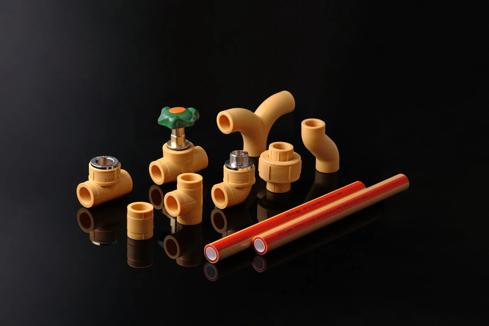
Five answers decide whether this detail is buildable, and a catalogue photograph carries none of them. Hitze publishes the PP-R range at OD 20–110 mm and the credential families behind it: DIN 8077/8078 and EN ISO 15874, SKZ testing on PP-R pressure pipe and fittings, DVGW type examination for drinking-water pipe, and an NSF laboratory BS 6920 report. Certificate numbers, the flange-adapter range and thread designations are confirmed per enquiry rather than printed. Treat the table below as that enquiry.
| Ask for | Why it decides the detail | How to verify it |
|---|---|---|
| Flange-adapter sizes and declared drilling standard | A PN16 ring will not bolt to a Class 150 ring | Written confirmation against ISO 9624:2019 plus the drilling standard, per OD |
| Thread designation per size and destination market | R, Rc, Rp and NPT do not interchange; 55° against 60° flanks | Designation on the drawing, plus a dry hand-engagement test on a sample |
| The manufacturer’s bolt-torque basis for its PP-R flange face | TN-38 values are PE seating stresses, not PP-R ones | A torque table stating the seating stress and nut factor it assumes |
| Lead time, split into stock and made-to-order | Transition parts are the long pole; the pipe rarely delays a job | Days ex-works per line item against your size mix, not one range for the order |
| Certificate scope per SKU | A credential held on pipe may not cover the fitting | Certificate reference and covered models, checked in the issuing body’s directory |
Source: compiled from the standards cited throughout this article. The right-hand column is what to request in writing; this article prints no supplier-specific torque, thread or lead-time figure it could not verify.
On lead time, ask what drives it rather than what it is. Three things usually do: whether the size is a stock line or a moulding run, whether the destination market needs a non-default thread or drilling variant, and whether certification paperwork for that SKU must be reissued. A supplier who answers those three can give a date that holds. Hitze’s position is no minimum order quantity with sample-friendly sourcing, so a sample of the exact transition part can be checked against the mating side first — the cheapest way to find a thread mismatch. Our certifications and compliance page sets out which credentials sit on which ranges.
Conclusion
PP-R and HDPE meet at a mechanical joint or they do not meet at all. Pick the route by diameter, then treat the transition part as the component that sets the rating of everything around it. The torque basis, the re-torque, the declared standard and the restraint are what the joint stands on.
If you are specifying a PP-R system that has to meet an HDPE main, send your size mix, the destination market and the mating standard on the HDPE side. We will come back with the parts that fit, the thread and flange designations in writing, and a sample to check before you commit.
Frequently asked questions
Can you butt-fuse PP-R to HDPE if you get the temperature right?
No. There is no correct temperature, because the melting windows do not overlap: HDPE is fully molten below 137 °C while isotactic PP melts between 160 and 175 °C. The polymers are also immiscible, so no entangled interface forms even where both surfaces are soft.
Is there an electrofusion coupler that joins PP-R to PE?
No qualified cross-polymer electrofusion coupler exists for this pair. An electrofusion coupler melts its own body into the pipe wall, which requires the same polymer on both sides. Treat any part offered for this purpose as unqualified until documentation is produced.
Which side should carry the flange adapter?
Both. A flanged transition uses a flange adapter fused to each pipe, each with its own loose backing ring, bolted face to face through a gasket. The requirement is that both rings share one declared drilling standard, such as EN 1092-1 PN16 or ASME B16.5 Class 150.
How tight should a PP-R threaded transition be?
One to two turns past hand-tight, never bottomed out, with counter-pressure applied to the fitting body. Published guidance for plastic threaded connections puts 10 to 25 ft-lb as adequate. Stop before the brass insert moves inside the PP-R body, because that damage is permanent.
Do I really have to re-torque a flanged transition?
Yes. PPI TN-38 specifies re-tightening about four hours after the first pass to final torque, and PP-R manufacturer guidance specifies within 24 to 48 hours. It compensates for seating of the plastic face, bolt creep and gasket compression-set, and skipping it is a common cause of a joint weeping after it passed its test.