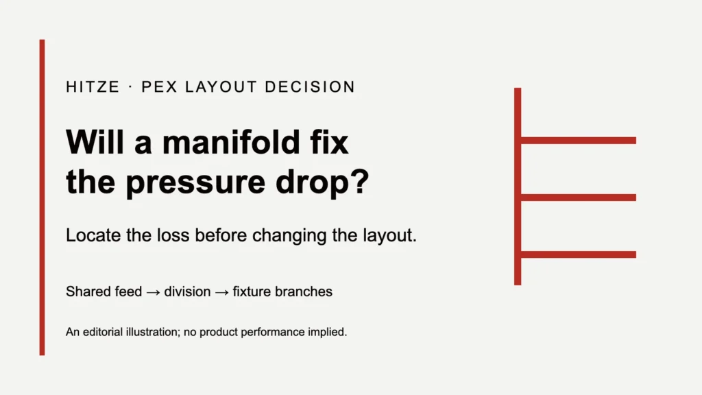
A PEX manifold can reduce pressure changes caused by fixtures sharing a downstream branch. It cannot remove losses in the service line, meter, regulator or common feed that still supplies every outlet. Before replacing a tee system, identify which part of the route loses pressure under simultaneous demand. A manifold helps when it removes that shared restriction; adding ports after the same upstream bottleneck leaves the bottleneck in place.
This is a layout decision for a plumbing designer considering a repipe or a new distribution system. It does not select a pipe diameter from a fixture count. The useful question is whether the proposed change alters the pressure path to the affected fixture, and whether the remaining path can deliver its required flow.
Key Takeaways
- Separate losses before the manifold from losses in each dedicated outlet line.
- A home-run line carries its fixture demand; the common feed carries the combined demand it serves.
- More stable pressure does not mean higher pressure or no pressure drop.
- A long, small home-run can have more single-fixture loss than a shorter branch.
- Compare flowing pressure and fixture flow under the same demand; a static reading cannot settle the layout choice.
- Retain a well-performing trunk or use a zoned layout when full home-runs add length without solving the restriction.
See a dedicated-route layout
Water Supply Piping (PEX Home Run Manifold), Mason Dixon Acres. A neutral owner-build example of route layout; the pressure decision rests on the sourced explanation below. Watch on YouTube.
Where fixtures still share a pressure path
Draw the water route from the building supply to the shower before comparing distribution blocks. Both layouts begin with common components: the service line, meter and any installed treatment, backflow or pressure-control equipment. Hot water also passes through its own supply and heating path. Separate fixture tubes begin only after their point of division. Everything before that division remains shared.
In trunk-and-branch plumbing, two fixtures can share an additional length of trunk downstream. Opening the second fixture increases the flow through that shared length. The first fixture then experiences the changed loss in that section as well as the loss in its own branch. Home-runs remove this particular shared downstream section by carrying each fixture from a common manifold through a dedicated tube.
The manifold still needs one supply. When several outlets run, the flow through the feed increases. A restriction before the split affects the pressure available to every outlet; separate tubes do not manufacture pressure at the split. This is why the position of the manifold matters to the proposed remedy. Replacing a group of tees with a block at the same location changes the fittings, but it does not automatically remove the pipe leading to them.
The distinction also explains an easy mistake in comparisons. A new home-run system may improve pressure because the repipe also replaces a restricted feed, shortens a route or changes its diameter. That result cannot be credited to the manifold alone. Compare the complete proposed route with the existing route and mark each changed component.
The 2026 PPI performance chapter identifies the service line, meter and utility pressure as limits on pressure at the riser base. Its tests compare the downstream layouts from that defined source. Treat the boundary of those tests as part of the result.
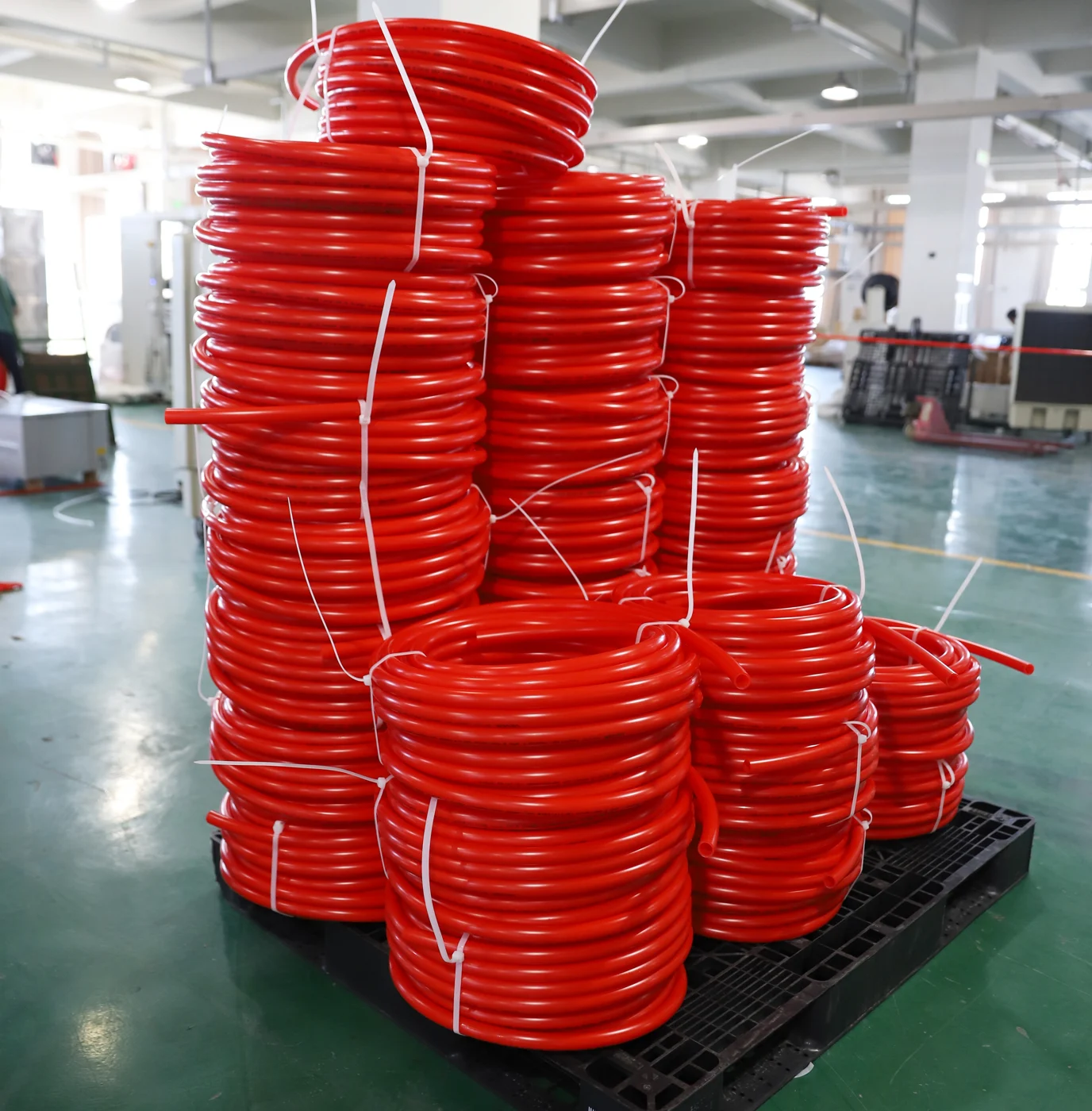
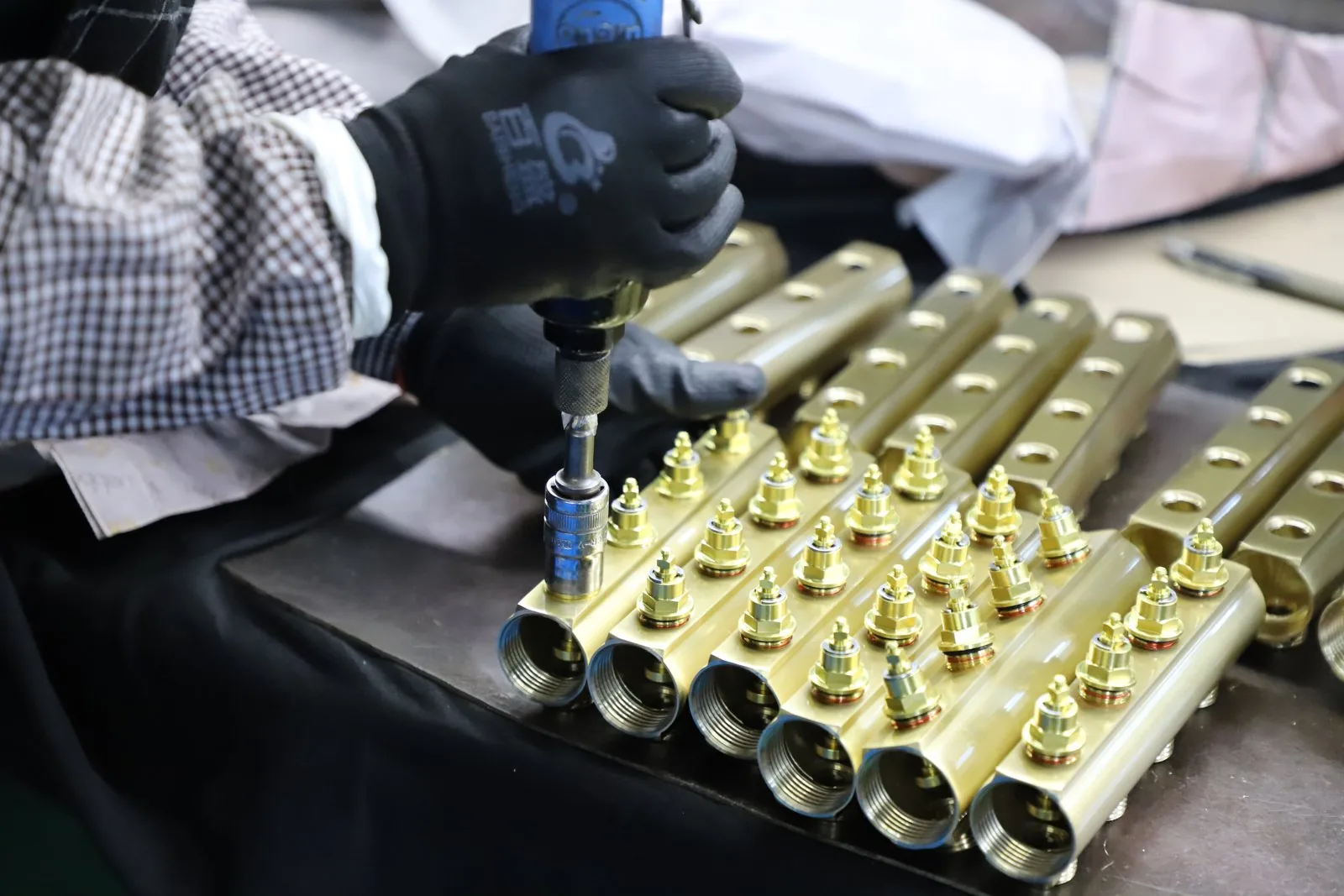
What the published tests actually show
“Steadier” and “stronger” answer different questions. Steadier describes how much pressure changes when other fixtures start running. Stronger describes the pressure available at a particular operating condition. A system can perform well on one measure and less well on the other.
PPI’s third-edition guide gives a useful bounded comparison. In Table 8.6, the test fixture was 100 feet from the source, with a 40 psi static source condition. The trunk-and-branch layout supplied the test fixture at a hot-side pressure of 31.6 psi when it operated alone and 28.6 psi with simultaneous fixtures. The parallel layout supplied 29.3 psi alone and 28.7 psi with simultaneous fixtures. These are published laboratory values, not Hitze test results or predictions for a house.
| Layout | Fixture alone (psi) | Simultaneous fixtures (psi) | Decision meaning |
|---|---|---|---|
| Trunk and branch | 31.6 | 28.6 | Higher alone; larger change under load |
| Zoned | 31.6 | 29.8 | Intermediate layout, specific test result |
| Parallel / home-run | 29.3 | 28.7 | Smaller change; lower pressure alone |
Source: PPI/PPFA/Home Innovation Research Labs, Chapter 8, Table 8.6. The guide reports a hot-side test-fixture flow of 1.7 US gallons per minute for these single and simultaneous conditions. Load combination: the remote tub/shower test fixture was full-on in shower mode, together with the second shower (full-on), kitchen faucet (mid-position), lavatory (both valves open) and tank-type water closet. Tables 8.2 and 8.4 identify this as TF+Sh2+Kit+Lav+WC; the remote test fixture was 15 feet above the source. The displayed pressures use the 100-foot configuration and 40 psi static source, not an arbitrary pair of open fixtures.
The parallel result does not support a promise of zero drop: its hot-side pressure changes from 29.3 to 28.7 psi. It does support the guide’s narrower conclusion about pressure stability under simultaneous use. It also challenges the assumption that switching layouts necessarily raises single-fixture pressure. In this configuration, trunk-and-branch started higher.
Use the comparison to identify the correct question, rather than copy the values into a specification. Route lengths, diameters, fittings, fixture demands and the supply condition determine your result. The chapter also discusses different test lengths and source pressures. One laboratory configuration cannot establish a universal minimum feed size or guarantee the same performance from an arbitrary manifold.
Which pressure pattern changes the decision
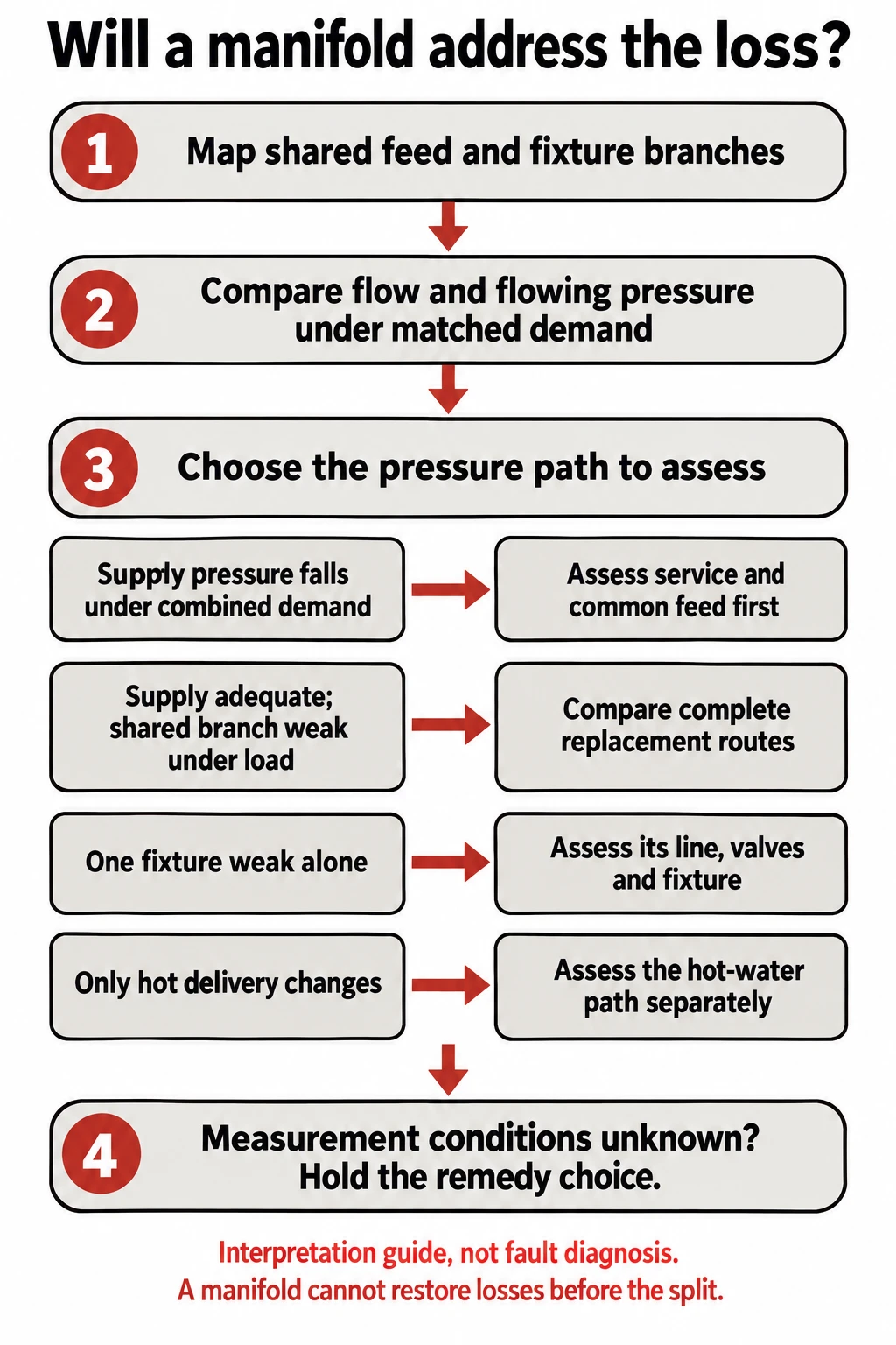
A fixture that performs poorly on its own presents a different problem from one that performs well alone and weakens only when a nearby outlet runs. Keep those conditions separate. The first may have an individual restriction or inadequate available supply; the second may expose a shared loss. Neither observation, on its own, identifies the faulty component.
The useful evidence is a matched record of fixture flow and flowing pressure at defined points, with the same outlet settings and demand combination. A competent plumber can select safe, suitable measurement points. A gauge read with outlets closed gives a static condition; it does not show the losses that appear while water moves. Compare the supply boundary and the affected branch under load rather than treating a single closed-system reading as proof of capacity.
| Observed pattern | Pressure path to assess | Layout implication |
|---|---|---|
| Supply-point pressure falls with combined demand | Service and common components before division | Downstream home-runs alone cannot restore supply-point pressure |
| Supply remains adequate; shared branch performs poorly under load | Shared downstream route and individual branches | Removing shared loss may help; calculate replacement routes |
| Only one fixture is weak even alone | Its line, valves and fixture restrictions | Do not justify whole-house redistribution from this observation |
| Only hot delivery changes | Hot supply, heater path and mixing arrangement | Assess hot path separately from cold distribution |
The second branch is where a manifold can be a useful design change. If the downstream shared route consumes the available pressure margin during combined demand, dedicated runs remove that shared section. But the benefit must survive the new individual routes. A much longer home-run can add its own loss and offset the gain from removing tees.
If pressure at the proposed manifold inlet already falls below what the fixtures need after their branch losses, redistribution is not the first remedy. Identify the common restriction or supply limitation first. Raising a regulator setting is not a substitute for establishing allowable pressure, component ratings and the actual cause; that decision belongs to the responsible installer and the applicable local requirements.
When the measurement points or demand conditions are unknown, hold the remedy choice. The missing information is specific: pressure at the division under the relevant demand, fixture flow, and loss along the affected route. Once these are known, the choice changes according to whether the avoidable loss lies before or after the proposed division. That is a usable decision boundary, even before a final diameter is selected.
Why a port count cannot size the feed
Counting outlets tells you how many connections the block needs. It does not determine the flow those outlets impose at the same time. A bank of lavatories, a bathtub and several high-demand fixtures can have the same port count and different supply requirements. The design demand must follow the accepted sizing method for the building and jurisdiction.
Apply that demand to each shared segment, then apply the individual fixture demand to its dedicated line. The available pressure at the fixture is the pressure entering the route minus the route’s losses, including elevation and components. Keep the boundary consistent: if the input is already measured at the manifold inlet under load, do not subtract the upstream losses again.
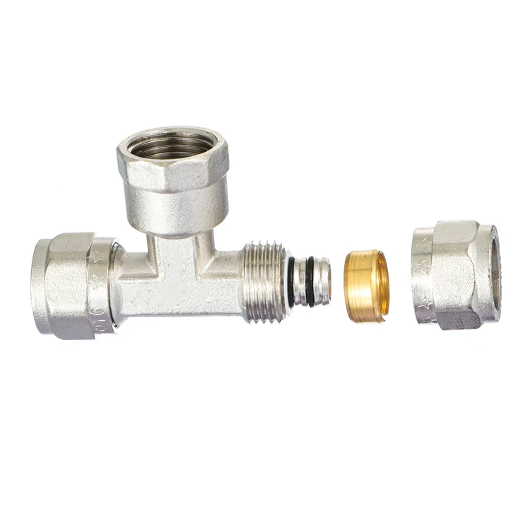
Diameter alone is also incomplete. PEX nominal size does not describe the full passage through every valve, adapter and manifold outlet. A selected assembly needs the pressure-loss data for its actual components and connection system. Two blocks with the same threaded inlet label can differ in their internal flow path. No supported conclusion about their hydraulic equivalence follows from the label alone.
The PPI design chapter treats pipe sizing and pressure drop separately from choosing the layout. It also warns that undersized piping can leave insufficient pressure at remote outlets, while oversized piping adds retained water and delays hot delivery. Enlarging every line sacrifices the small-volume benefit without proving that the enlarged section was the restriction.
For an actual selection, use the current supplier dimensions and hydraulic data with the accepted design method. The PPI Plastic Pipe Design Calculator can assist with pipe pressure-loss estimates; it does not identify an unknown valve loss or replace project sizing approval. Hitze’s PEX pipe range is the relevant product starting point when a dedicated flexible route fits the design. Product and fitting compatibility still require the proposed system’s current documentation.

Choose the scope of the change
A full home-run arrangement earns its extra routes when dedicated fixture lines solve a shared downstream restriction or provide needed individual isolation. It is less persuasive when the existing branches already deliver the required flow and the real loss lies upstream. Keep a layout that works unless the change produces a defined benefit.
For fixtures clustered around a remote bathroom, a zoned arrangement may avoid routing every line back to a distant central block. It still has a shared trunk to the zone, so its benefit depends on that trunk and the short branches it supplies. PPI’s design guide recognizes trunk-and-branch, parallel and zoned layouts. Choosing among them is a balance of routing and performance, rather than a ladder from bad to good.
Include service access in that choice. Individual isolation is a real advantage of a valved manifold only if someone can reach and identify its valves. The guide requires accessible locations for valved manifolds. A cabinet behind a removable access panel serves a different maintenance task from a block sealed behind a finished wall.
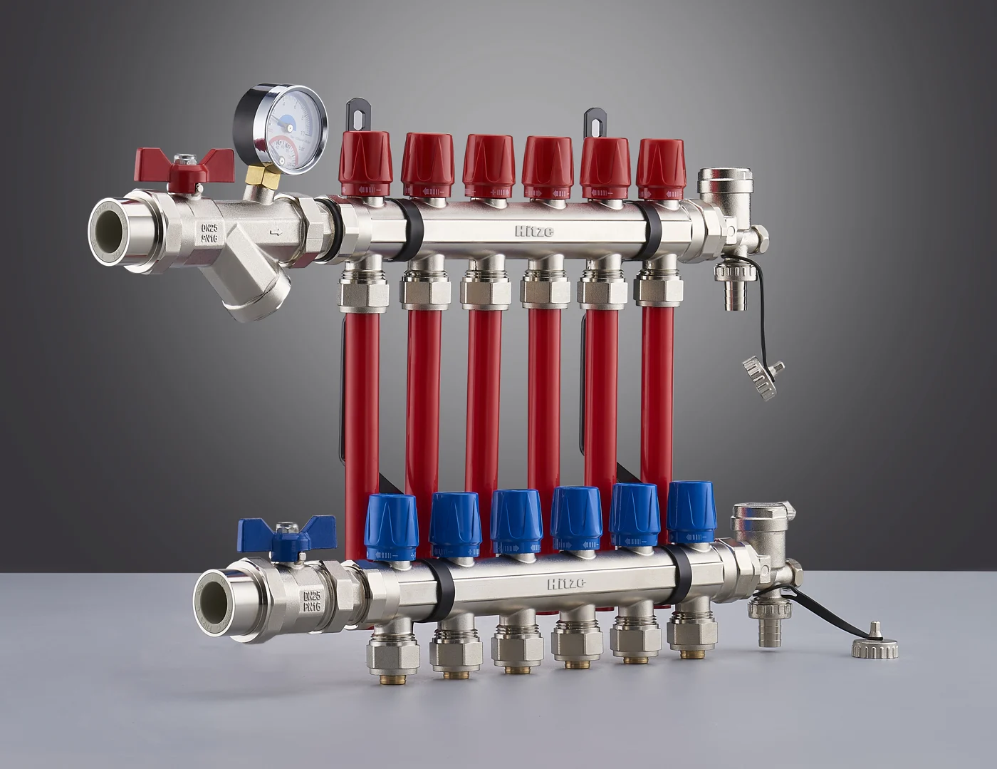
At the decision point, write the proposed benefit in one sentence: “This change removes the shared bathroom branch while retaining a verified adequate feed,” or “This change provides individual isolation but does not address the supply limitation.” That statement makes the scope testable. It also keeps the purchase from expanding into a whole-house repipe merely because a manifold looks more organized.
Copy this model-data request
Country / applicable code: ____; potable-water or heating duty: ____; water temperature: ____.
Dynamic pressure at proposed manifold inlet: ____ [unit], measured with ____ fixtures operating.
Simultaneous demand: fixture ____ / flow ____ [unit]; fixture ____ / flow ____ [unit].
Branches: fixture ____ / route length ____ [unit] / actual internal bore ____ [unit] / fittings and valves ____.
Required flow and minimum pressure at the affected fixture: ____; proposed inlet/outlet connections: ____.
Please identify the exact candidate manifold and configuration, then provide its pressure-loss curve or data at these flows and stated test conditions. Identify included valves/adapters and provide the relevant tube/fitting compatibility documents. If the hydraulic data or potable-water scope is unavailable, state that gap; an inlet size or port count cannot close the selection. Discuss delivery only after the product, quantity and required date are defined.
For plumbing contractors and project designers with a defined PEX route Send the actual dynamic pressure at the proposed manifold inlet, the simultaneous fixture-flow combination, and each affected branch’s length and internal bore. Ask which exact manifold model and assembled connection system, if any, have pressure-loss data covering that duty. The project designer retains the pressure-budget and sizing decision.
Conclusion
Before choosing a manifold, locate the pressure loss, compare the complete old and new routes, and check the remaining common feed at the relevant demand. Accept redistribution as a pressure remedy only when it removes the limiting shared section without creating an inadequate individual run. Otherwise address the supply or local restriction, and choose a manifold for its separate service-access benefit if that benefit is needed.
Frequently Asked Questions
Does a manifold increase incoming water pressure?
No. A passive manifold distributes the supply it receives. It may reduce downstream interaction, but it does not raise the pressure arriving from the service and common feed.
Can equal-length home-runs guarantee equal fixture flow?
No. Flow also depends on bore, fittings, outlet restrictions and fixture demand. Equal length removes only one difference between the routes.
Is a larger common feed always the correct fix?
No. Enlarge a feed only when sizing shows it is the limiting section. A restricted valve, fixture or supply condition can remain limiting after a pipe-size change.
Can a radiant-heating manifold serve potable home-runs?
Do not assume so. Verify drinking-water suitability, ratings and connection compatibility for the exact assembly; heating flow meters and balancing valves do not establish potable suitability.